MAN00000772_SI-G200BB_SVCPDFA.pdf - 第14页
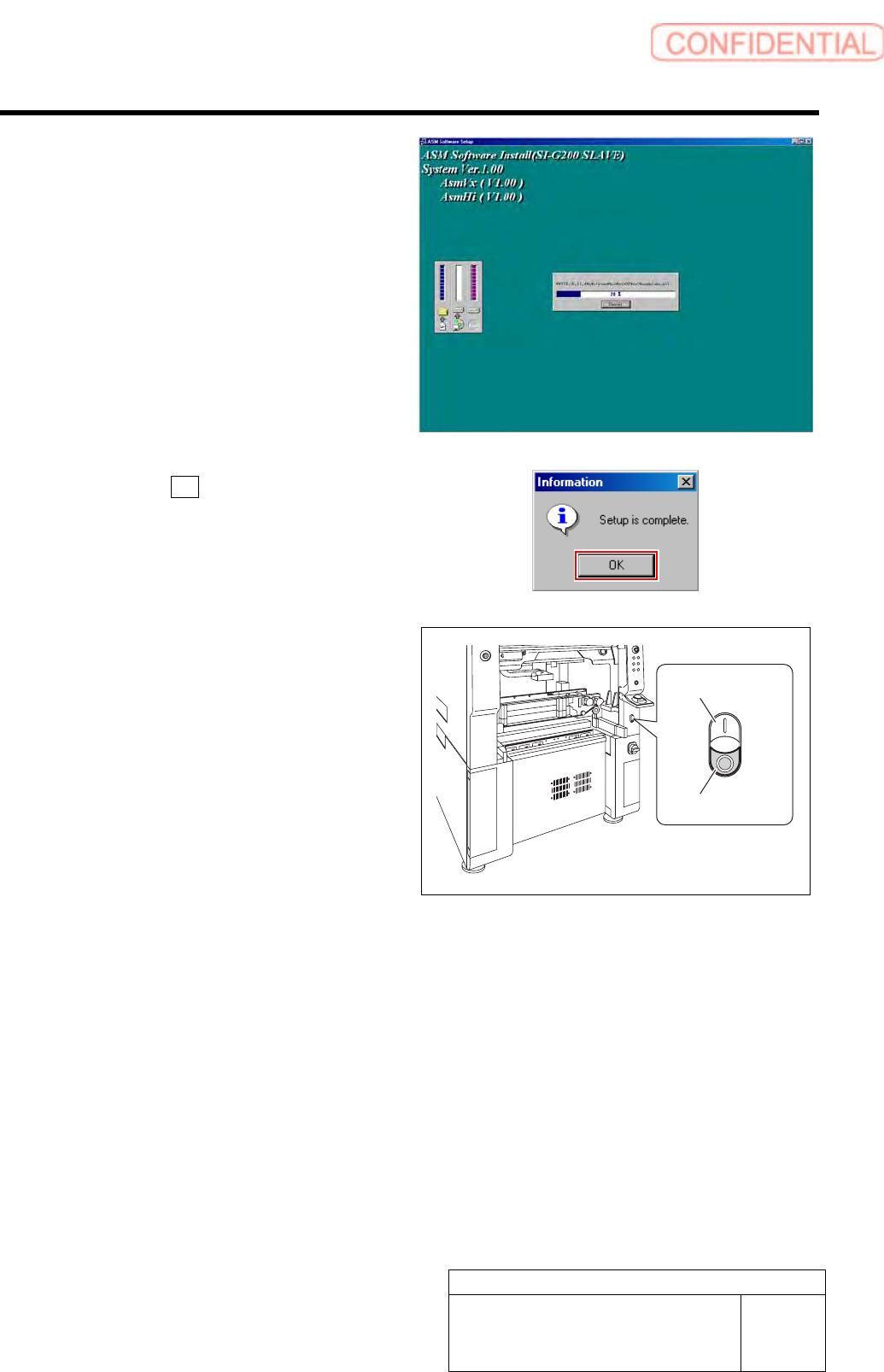
Work Procedure WKGB-10101-01 Installin g System Sof tware SHEET 8/8 Installation of th e system softwar e is started. When installation is ende d, Information dialog box appears. 7. Click the OK button on the Informa - t…
Work Procedure
WKGB-10101-01
Installing System Software
SHEET
7/8
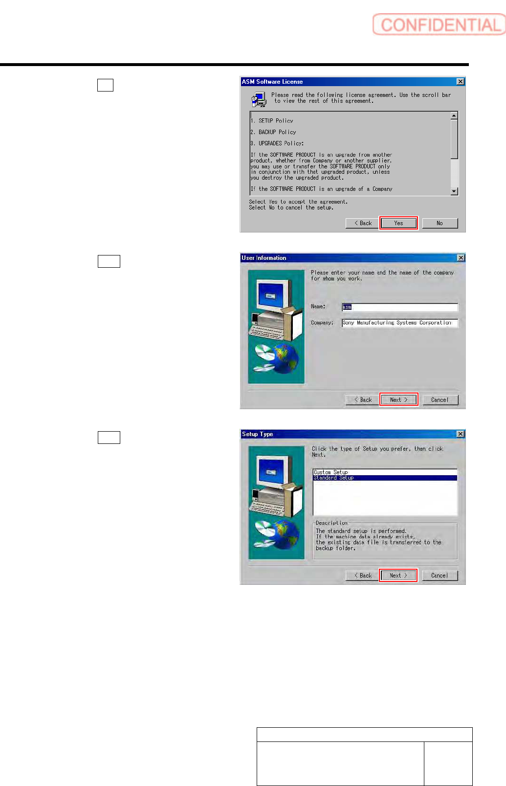
4. Click the Yes button on the ASM Soft-
ware License screen.
5. Click the Next button on the User In-
formation screen.
6. Click the Next button on the Setup
Type screen.
Work Procedure
WKGB-10101-01
Installing System Software
SHEET
8/8
Installation of the system software is started.
When installation is ended, Information dialog
box appears.
7. Click the OK button on the Informa-
tion dialog box.
8 Re-start the unit.
1. Close the Installer screen.
2. Close the explorer window.
3. Press the power off switch.
Shutting down of the system starts and the power
is automatically shut off.
4. Press the power on switch.
The unit starts, and the system software auto-
matically starts up.
9 Check that the system software normally
operates.
10 Delete the “AutoStarter” file which was
evacuated to the other folder.
Power on switch
Power off switch
Work Procedure
WKGB-10102-01
G200BB Head Maintenance
SHEET
1/11
G200BB Head Maintenance
This document explains the G200BB head maintenance procedure.
Follow the same procedure to perform maintenance on the front head and rear head.
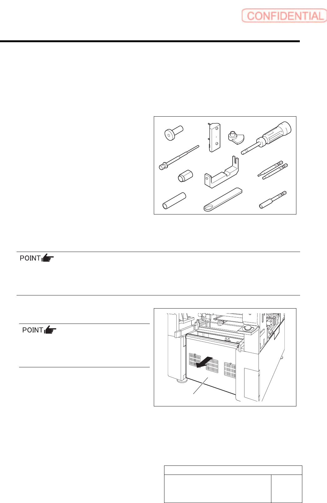
[Necessary jigs]
A Pulling jig
B Spline nut assembling jig (1)
C Spline nut assembling jig (2)
D Bearing press fitting jig
E Gear phase adjustment jig (1)
F Gear phase adjustment jig (2)
G Spring holding hook
H Spacer assy retainer
I Torque screwdriver
(6[cN•m] to 40 [cN•m])
J Bit for torque screwdriver
(1.27 [mm], 2.5 [mm])
K Bit for air screwdriver
(width across flats: .5 mm)
[Disassembling Procedure]
To assure the mounting accuracy, the inner shaft is strictly paired with the ball bush guide unit and the
collar when the system is manufactured. In order not mix the disassembled parts with those for other
Indexes, control the parts separately by each Index. When reassembling, assemble the original parts and
attach them to the original index.
1 Turn off the VACUUM breaker.
Turn OFF the VACUUM breaker before
removing the mechanical valve in order to
prevent suction of contaminant and dust from
the mechanical valve.
1. Loosen the screws (2-+T4×8) to
remove the lower cover on the back of
the unit.
E
F
I
K
D
C
B
A
J
Lower cover
G
H