MAN00000772_SI-G200BB_SVCPDFA.pdf - 第234页
Calibration HLGB-10308-01 Pickup Check Camera Calibration SHEET 4/5 Check that the detection r esolution check jig is displayed on the HEIGHT DISPLA Y at this tim e. When measurement of the detection resolution check jig…
Calibration
HLGB-10308-01
Pickup Check Camera Calibration
SHEET
3/5
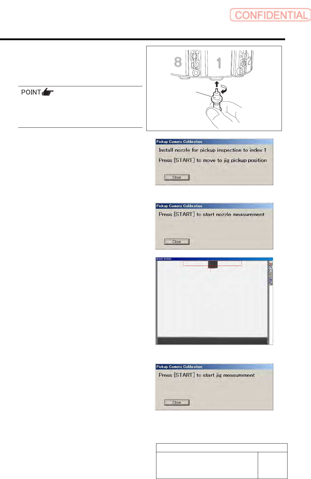
7 Install the length reference nozzle jig to the
turret No.1 and press the [START] button on
the operation panel.
When installing the nozzle, insert it while
slowly turning.
After inserting the nozzle, check that it is not
drawn out by pulling downward.
The length reference nozzle jig moves to the
measuring position and “ Press [START] to start
nozzle measurement” is displayed on the message
screen.
8 Press the [START] button on the operation
panel.
Length reference nozzle jig measurement is
performed and “ Press [START] to start jig
measurement” is displayed on the message screen.
Check that end of the reference jig nozzle is displayed
on the HEIGHT DISPLAY at this time.
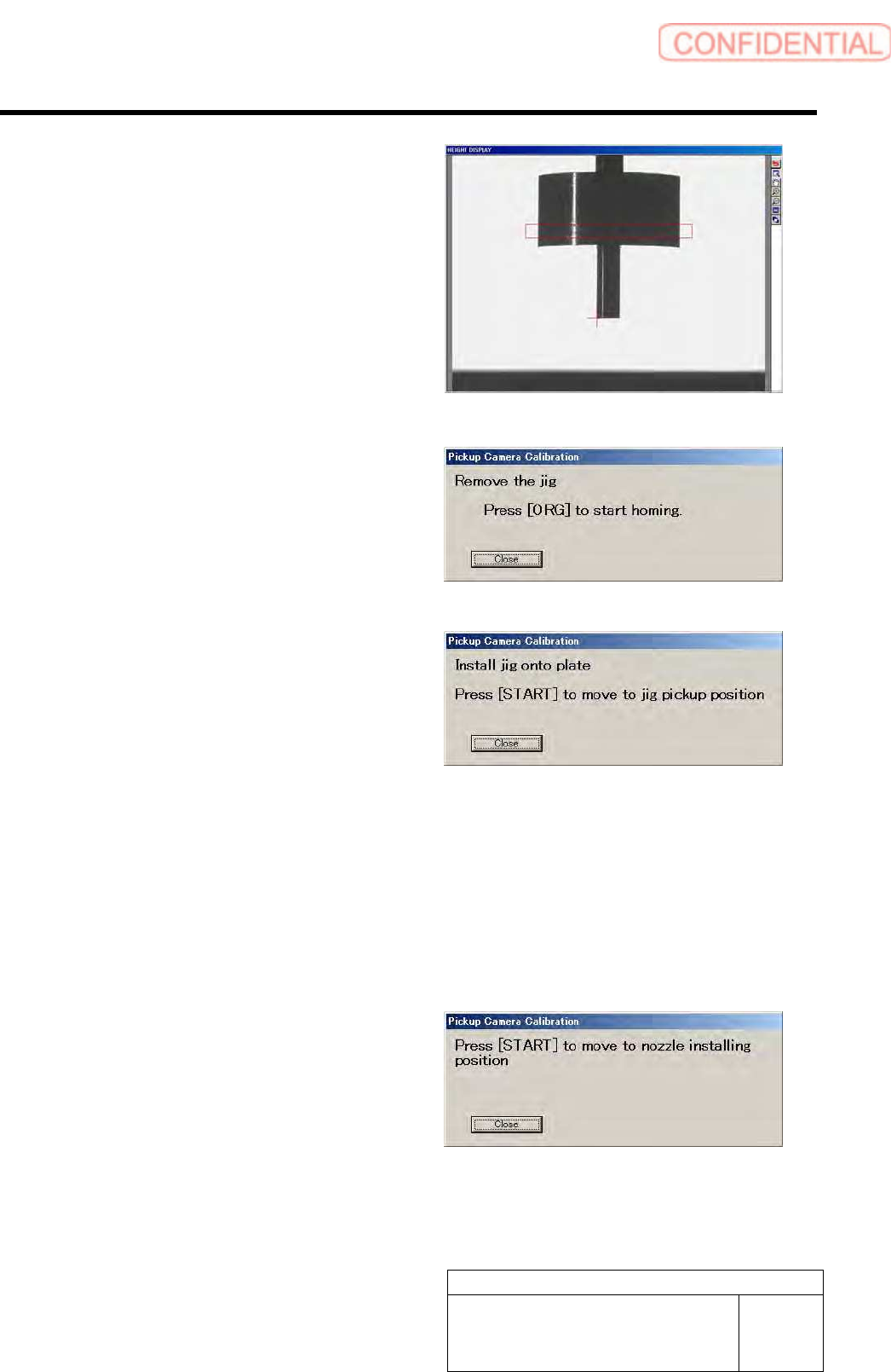
9 Press the [START] button on the operation
panel.
The reference position nozzle picks up the detection
resolution check jig, and measurement is made.
Length reference
nozzle jig
Calibration
HLGB-10308-01
Pickup Check Camera Calibration
SHEET
4/5
Check that the detection resolution check jig is
displayed on the HEIGHT DISPLAY at this time.
When measurement of the detection resolution check
jig is ended, the head moves to the supply section.
10 Remove the detection resolution check jig
from the nozzle and press the [ORG] button
on the operation panel.
Origin position return is performed and “Install jig
onto plate” is displayed on the message screen.
11 Continuously, make a second jig
measurement.
1. Again set the pickup check resolution
inspection jig onto the calibration
plate jig and press the [START] button
on the operation panel.
The length reference nozzle jig moves to the
measuring position and “Press [START] to start
nozzle measurement” is displayed on the
message screen.
2. Perform operations from nozzle
recognition to jig measurement
similarly to the procedure 8 to 9.
12 When the second measurement is ended,
press the [START] button to move the head
to nozzle installing position.
Turret No.1 moves to the nozzle installing position
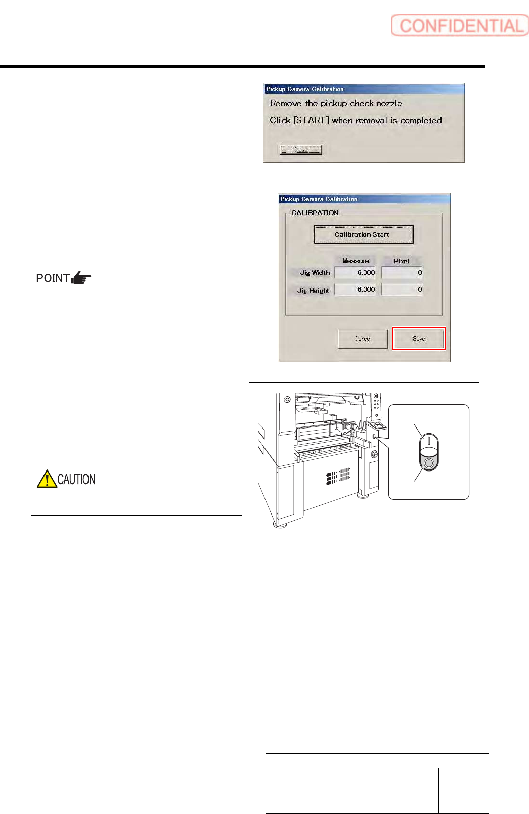
and “Remove the pickup check nozzle” is displayed
on the message screen.
Calibration
HLGB-10308-01
Pickup Check Camera Calibration
SHEET
5/5
13 Remove the length reference nozzle jig and
press the [START] button on the operation
panel.
The message screen closes and returns to the Pickup
Camera Calibration screen.
14 Click the Save button on the Pickup Camera
Calibration screen.
Calibration information is saved and the Pickup
Camera Calibration screen closes.
In order to store the calibration result in the
unit, be sure to re-start the unit before
operating the unit.
15 Re-start the unit.
1. Close the Calibration screen.
2. Press the power off switch.
Shutting down of the system starts and the power
is automatically shut off.
Do not shut down the power from the start
menu of Windows
®
.
3. Press the power on switch.
The unit starts in a state that the pickup camera
calibration result is reflected on the system.
Power off switch
Power on switch