MAN00000772_SI-G200BB_SVCPDFA.pdf - 第279页
Calibration HLGB-10314-01 XY A xis Sof tware Limit Setup SHEET 11 / 11 4. Click in an order of M/ C SETUP men u ORG OFFSET tab XY butto n. XY Axis screen is displayed. 5. Click the Jog Move button. 6. Press the upper…
Calibration
HLGB-10314-01
XY Axis Software Limit Setup
SHEET
10/11
5. Click the Jog Move button.
6. Press the lower cursor to jog-move Y
axis in negative direction.
When Y axis moves to the software limit
position, alarm is displayed.
7. Press the [RESET] button on the
operation panel to cancel the alarm.
8. Check that the present position of Y
axis displayed on the operation screen
of XY axis is same as the value
calculated in the setup procedure 1.
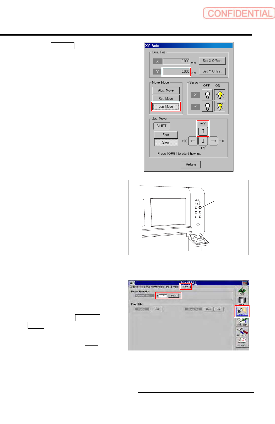
2 Press the [FRONT] button on the operation
panel on the front side.
Operation right moves to the front side.
3 Check Y coordinate of the software limit
sensor in Y axis positive direction on the
front side.
1. Press the [ORG] button on the
operation panel to perform origin
position return.
2. Click in an order of MANUAL menu
CASS. tab.
Cassette operation screen is displayed.
3. Input “101” into the cassette position
input box and click the Move button.
The head moves to the cassette position “101”.
FRONT button
Calibration
HLGB-10314-01
XY Axis Software Limit Setup
SHEET
11/11
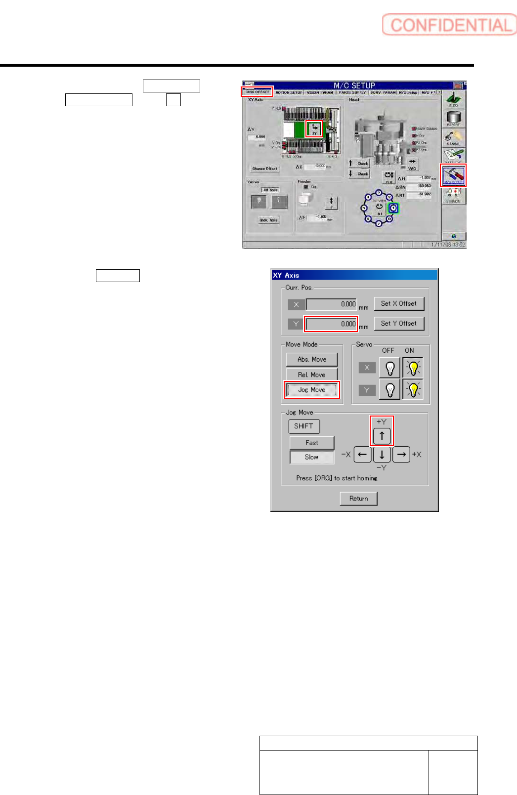
4. Click in an order of M/C SETUP menu
ORG OFFSET tab XY button.
XY Axis screen is displayed.
5. Click the Jog Move button.
6. Press the upper cursor to jog-move Y
axis in positive direction.
When Y axis moves to the software limit
position, alarm is displayed.
7. Press the [RESET] button on the
operation panel to cancel the alarm.
8. Check that the present position of Y
axis displayed on the operation screen
of XY axis is same as the value
calculated in the setup procedure 1.
9. Press the [ORG] button on the
operation panel to perform origin
position return.
Calibration
HLGB-10315-01
Conveyor Width Adjustment
SHEET
1/2
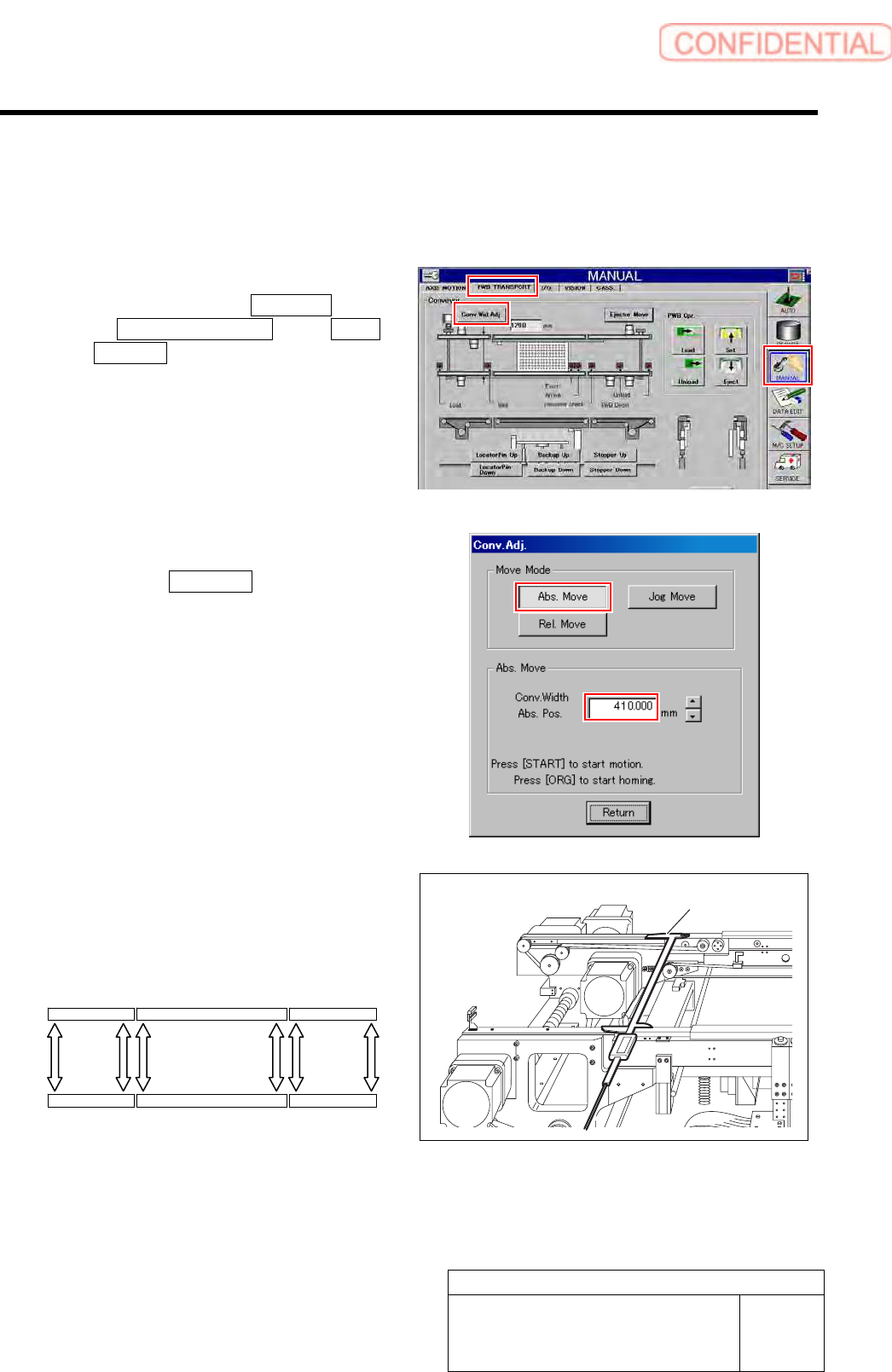
Conveyor Width Adjustment
[Procedure]
1 Perform origin position return of conveyor.
1. Click in an order of MANUAL menu
PWB TRANSPORT tab Conv.
Wid. Adj. button.
Conv. Adj. screen is displayed.
2. Press the [ORG] button on the
operation panel with the Conv. Adj.
screen being displayed.
Conveyor return to origin.
2 Set the conveyor width to 410 mm.
1. Click the Abs. Move button on the
Conv. Adj. screen.
2. Input “410” into the input box of the
Conv. Width Abs. Pos.
3. Press the [START] button on the
operation panel.
Conveyor width is widened to the position of 410
mm.
3 Measure conveyor width on the following six
locations with digital caliper.
Take notes of measured values.
Digital caliper
Conveyor L Middle conveyor Conveyor R
(1) (2) (3) (4) (5) (6)