MAN00000772_SI-G200BB_SVCPDFA.pdf - 第298页
Adjustment HLGB-10404-01 Adjustment of H A xis Upper End OT Sensor (H-CCW) SHEET 1/3 Adjustment of H Axis Upper End OT Sensor (H-CCW) Perform this working on both heads on the front sid e and rear side. [Necessary jigs] …
Adjustment
HLGB-10403-01
H Axis Gear Z-phase Matching
SHEET
5/5
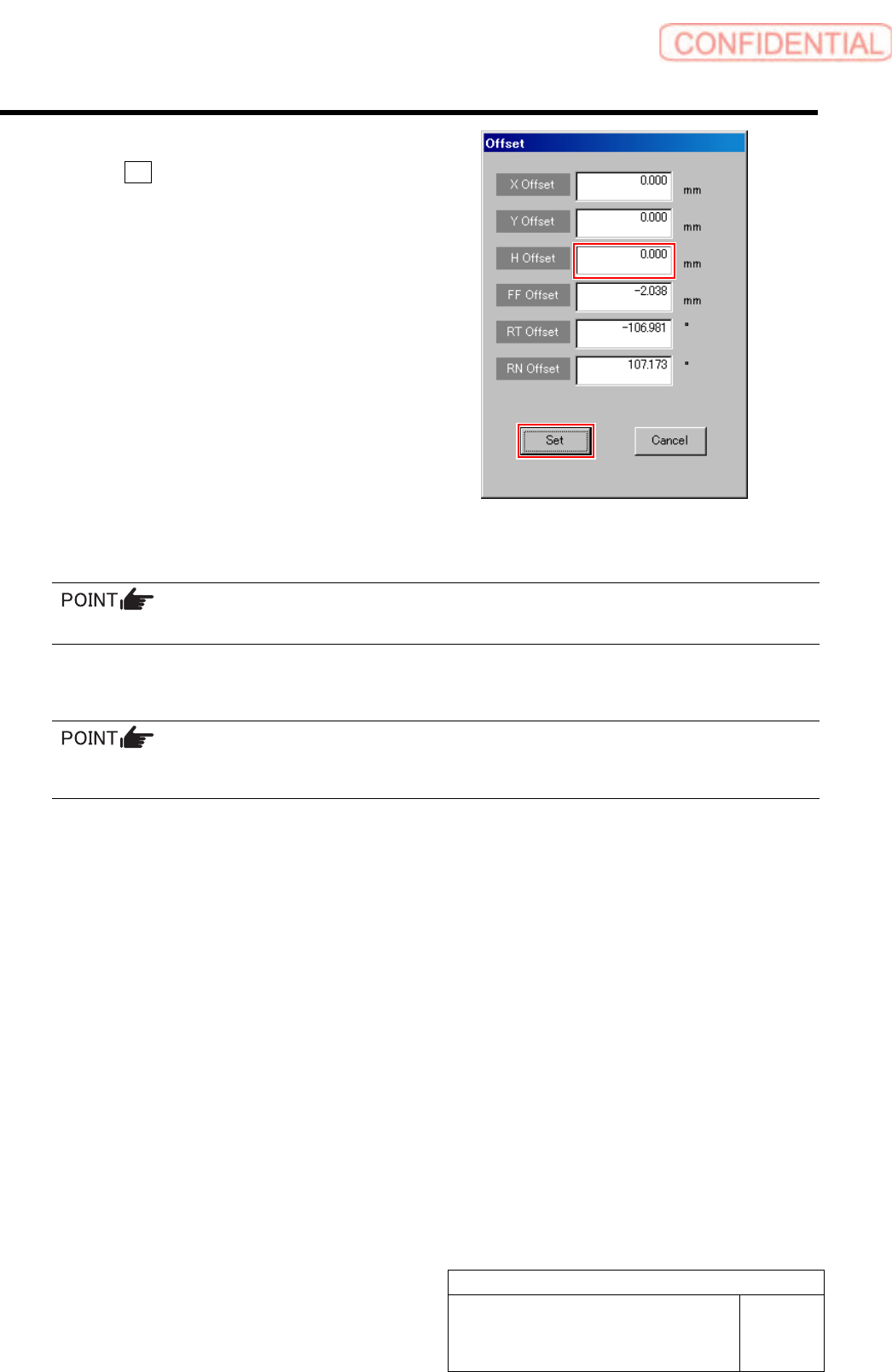
2. Input “0” in the H Offset box, and click
the Set button.
H offset value is set, and the Offset screen closes.
3. Press the [ORG] button on the
operation panel with the RN/H axis
screen displayed.
Origin position return is performed for the H axis
only.
12 Check that the clearance between the H axis pusher and inner shaft is 1.0 to 1.1 mm by thickness
gauge.
Unless the clearance is 1.0 to 1.1 mm, it is necessary to re-perform “H axis origin position setup”.
13 Install the H axis lower end sensor (H-CW).
Perform position adjustment of the lower end sensor (H-CW) in the post-process of “Adjustment H axis
lower end OT sensor (H-CW)”.
14 Return the servo parameter of the H axis to the previous value.
Return the H axis parameter changed in the procedure 3-6 to the previous value.
That’s the end of H axis gear Z phase matching.
15 After H axis gear Z phase adjustment, perform the following work.
1. Adjust OT sensor at the upper end of H axis.
For work procedure, refer to “Adjustment of H Axis Upper End OT Sensor (H-CCW) [HLGB-10404-01]”.
2. Adjust OT sensor at the lower end of H axis.
For work procedure, refer to “Adjustment of H Axis Lower End OT Sensor (H-CW) [HLGB-10405-01]”.
3. Set H axis origin position.
For work procedure, refer to “H Axis Origin Position Setup [HLGB-10202-01”.
Adjustment
HLGB-10404-01
Adjustment of H Axis Upper End OT
Sensor (H-CCW)
SHEET
1/3
Adjustment of H Axis Upper End OT Sensor (H-CCW)
Perform this working on both heads on the front side and rear side.
[Necessary jigs]
• H Axis sensor adjusting Jig
(L=26.6 mm, 26.5 mm)
• Thickness gauge (t=1.6 mm)
[Procedure]
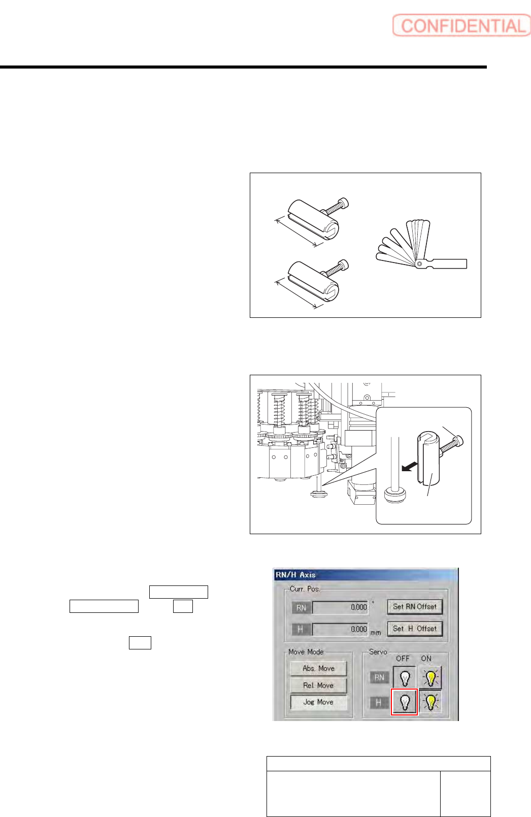
1 Install the H axis sensor adjusting jig to the
inner shafts of turrets No.2 and No.8.
1. Push down the inner shaft of the
turret No.2 and pinch the H axis
sensor adjusting jig (L=26.6 mm)
between the turret and inner shaft.
2. Push down the inner shaft of the
turret No.8 and pinch the H axis
sensor adjusting jig (L=26.5 mm)
between the turret and inner shaft.
3. Remove the cap screw for H axis
sensor adjusting jig.
2 Turn off the H axis servo.
1. Click in an order of M/C SETUP menu
ORG OFFSET tab R.H button.
RN/H Axis screen is displayed.
2. Click the servo OFF button for H axis.
Servo for H axis is turned off.
H axis sensor adjusting jig
26.6 mm
26.5 mm
H axis sensor
adjusting jig
Cap screw
Thickness gauge
Adjustment
HLGB-10404-01
Adjustment of H Axis Upper End OT
Sensor (H-CCW)
SHEET
2/3
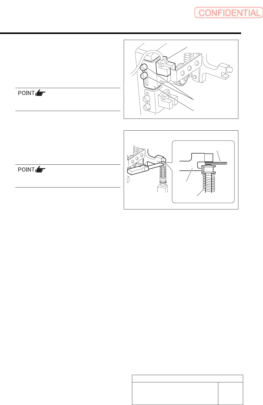
3 Loosen the cap screws (2-M3) on sensor
bracket for the H axis upper end OT sensor
to move the bracket downward (to lower
end).
The H axis upper end OT sensor is obstructed by the
dog, and the LED lights off.
Keep the cap screws (2-M3) in temporarily
tightened state.
4 Push down the H axis pusher by hand, place
a thickness gauge of 1.6 mm on the inner
shaft (No.1), and pinch with the H axis
pusher.
When pinching the thickness gauge, slightly
bring up the inner shaft from the lower.
5 Move the sensor bracket for the H axis
upper end OT sensor upward little by little,
tighten the cap screws (2-M3) at a position
of boundary where the lighting LED
extinguishes, and secure the sensor
bracket.
6 Remove the thickness gauge.
When the thickness gauge is removed, the LED for
the H axis upper end OT sensor lights up.
7 Remove the H axis sensor adjusting jig
installed on the turrets No.2 and No.8.
Sensor bracket
Cap screw
H axis upper end OT sensor
Thickness gauge
H axis pusher
Inner shaft