4OM-1345-009_w.pdf - 第106页
1-50 AKHEMT -ID 4.3 Replacement of Fluorine Sheet and Urethane Clamp T ime of Replacement It is recommended that they should be replaced once a year . Replacement Procedure (1) Zero the cutter . Reference Refer to "…
1-49
AKHEMT-ID
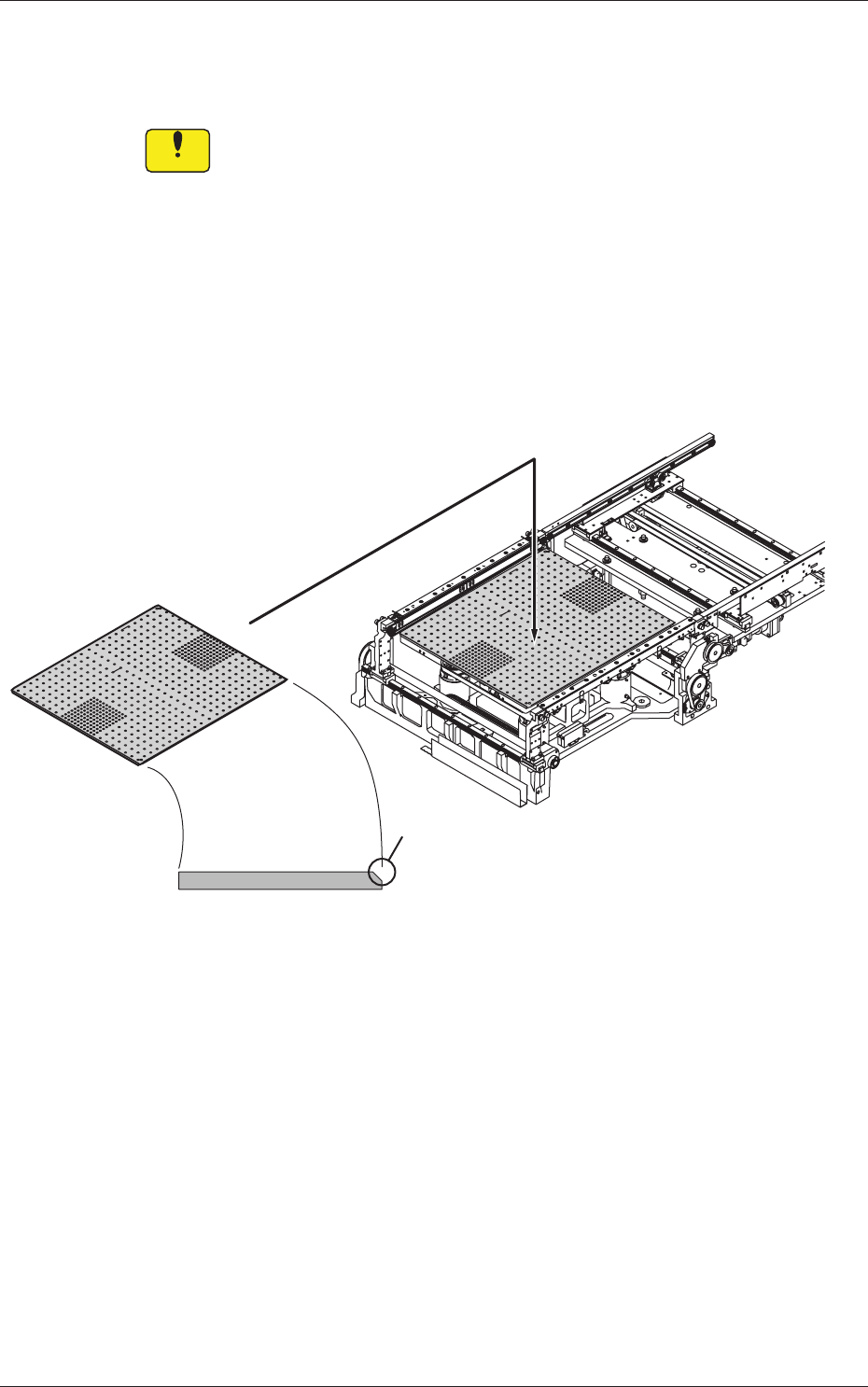
(7) Attach the backup plate to the backup base board so that the
chamfered side of the backup plate can be seated toward the central
side of the machine.
Notice
(a) Attach the backup plate so that the chamfered side can be
seated toward the central side of the machine.
If the plate is not attached correctly, the machine will break
down.
(b) Do not allow any foreign substance to be trapped between
the backup base board and the backup plate. Otherwise, the
machine will break down.
(c) After the backup plate has been attached, confi rm that it is
seated fi rmly without any play, is not tilted, and is directed
correctly.
Set up the backup plate so that the chamfered
side can be seated toward the right side of
the machine.
Chamfered Side
Fig. 4A46
0602-001
4.2 Lubrication for Ball Screw Splines
1-50
AKHEMT-ID
4.3 Replacement of Fluorine Sheet and Urethane Clamp
Time of Replacement
It is recommended that they should be replaced once a year.
Replacement Procedure
(1) Zero the cutter.
Reference
Refer to "4.4 "CUTTER ADJ" Window" in "Chapter 4 (Vol. 2)" for the
zeroing operation of the cutter.
(2) Move down the feeder base and detach the bank feeder change cart.
(3) Turn off the power to the machine.
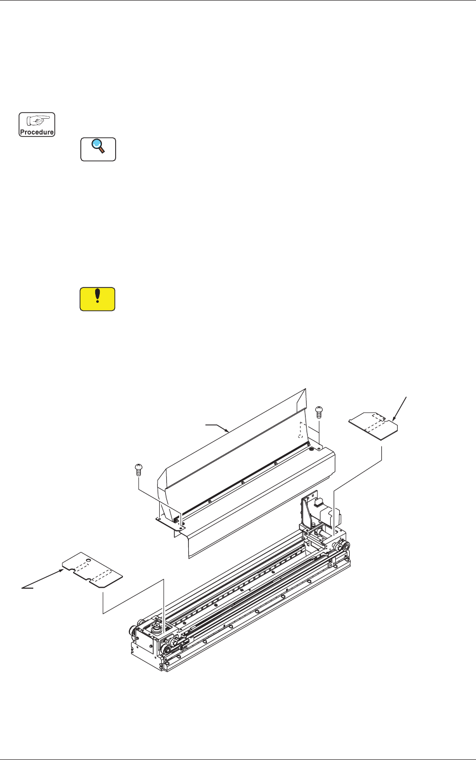
(4) Open the cover.
(5) Detach the transparent cover (origin and motor sides) and the tape
guide.
Notice
(a) Carefully detach or attach the tape guide to avoid the Y-axis
linear scale being scratched.
(b) When the cutter is not located at its origin, the tape guide
cannot be detached because the fl uorine sheet is caught by the
tape clamp.
Tape Guide
Transparent Cover
(Motor Side)
Transparent Cover
(Origin Side)
Fig. 4A48
0602-001
4.3 Replacement of Fluorine Sheet and Urethane Clamp
1-51
AKHEMT-ID
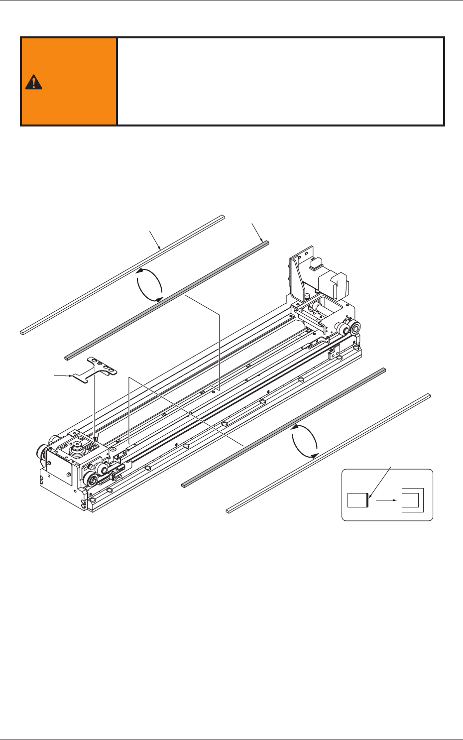
(6) Attach the cut unit fi xing Jig.
WARNING
WARNING
Pay close attention to the cutter blade during the maintenance
work.
•
Lack of attention will result in a hand injury, etc.
•
Be sure to attach the fi xing jig to the cut unit during the
maintenance work for safety purposes.
(7) Detach the urethane clamp from the tape clamp.
(8) Peel off the double-faced tape of a new urethane clamp and attach a
new urethane clamp to the tape clamp.
New Urethane Clamp
Old Urethane Clamp
Double-Faced Tape Side
View (Attachment Direction)
from Side Face
Cut Unit
Fixing Jig
Fig. 4A49
0602-001
4.3 Replacement of Fluorine Sheet and Urethane Clamp