4OM-1345-009_w.pdf - 第219页
5-2 AKHEMT -ID 0605-001 Failures can further be classi fi ed as shown in the table below . T able 4E1 Classi fi cation of Failures Contents of Failures Symptom of Failures Failure before Component Placement Component Picku…
5-1
AKHEMT-ID
0605-001
1. Classifi cation of Failure Symptoms and Helpful Hints on Countermeasures against Failure
1. Classifi cation of Failure Symptoms and Helpful
Hints on Countermeasures against Failure
1.1 Classifi cation of Failure Symptoms
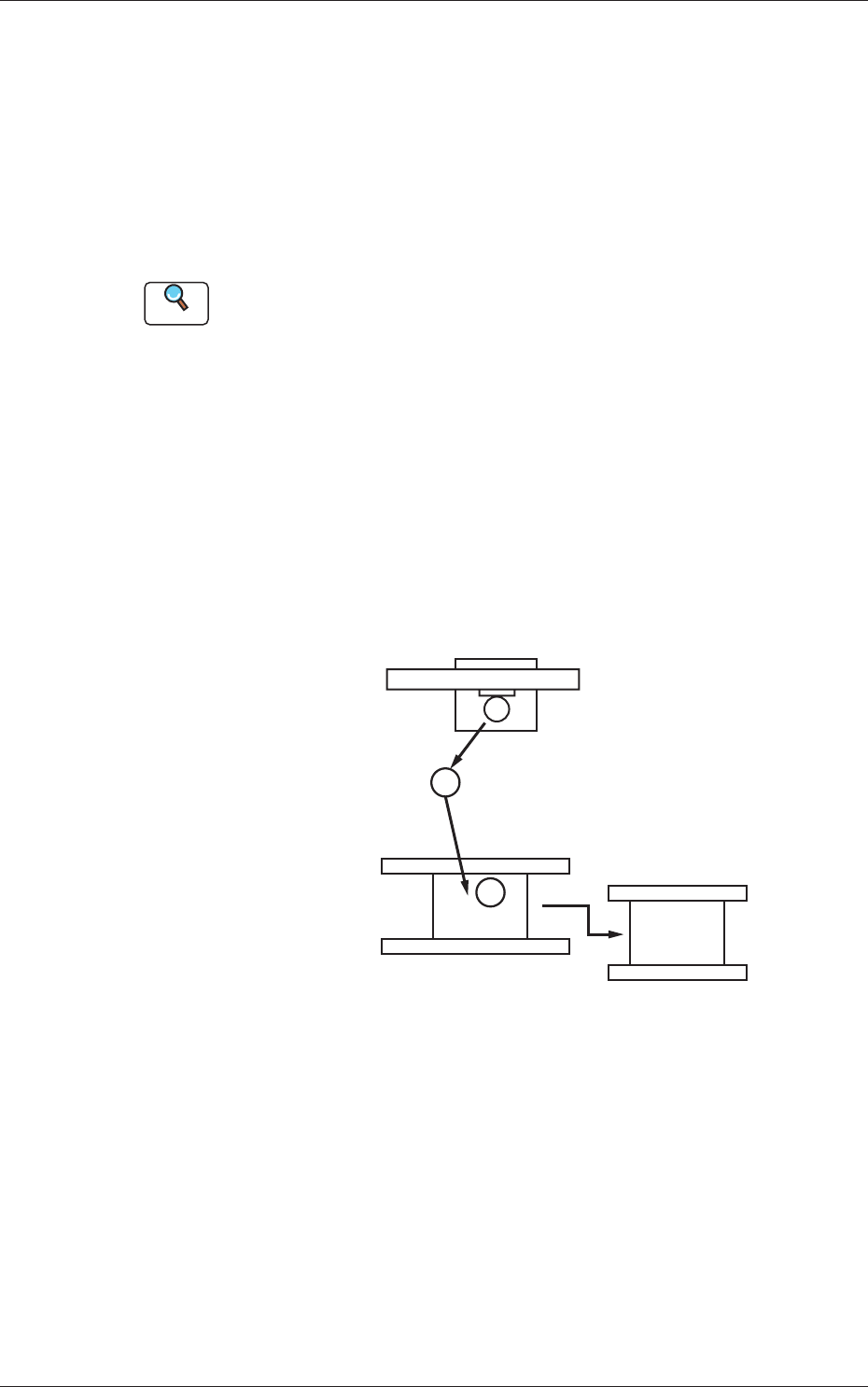
The machine processes can be classifi ed into Processes A, B, C, D, and E as
shown below.
Reference
Refer to "3. Surface Mounting Mechanism" in "Chapter 1 (Vol. 1: Guide)"
for the outline of actions.
Process A : The placement head moves to the feeder base and picks up
a component.
Process B : The head moves to the area where the component
recognition camera is installed and a component
recognition process is taken there.
Process C : The placement angle is corrected while the head is moving
to the PCB positioning section.
Process D : The component is placed on the PCB.
Process E : The component-placed PCB is discharged.
1
2
3
Feeder Base Section
Component Recognition Camera
PCB Positioning Section
Process A
Process B
Process C
Process D
Process E
Fig. 4E1
Based on these processes, failures can be divided roughly into the following
two types.
Failure before Component Placement : This type of failure occurs
mainly in Processes A, B, and
C.
Failure after Component Placement : This type of failure occurs
mainly at Processes D and E.
5-2
AKHEMT-ID
0605-001
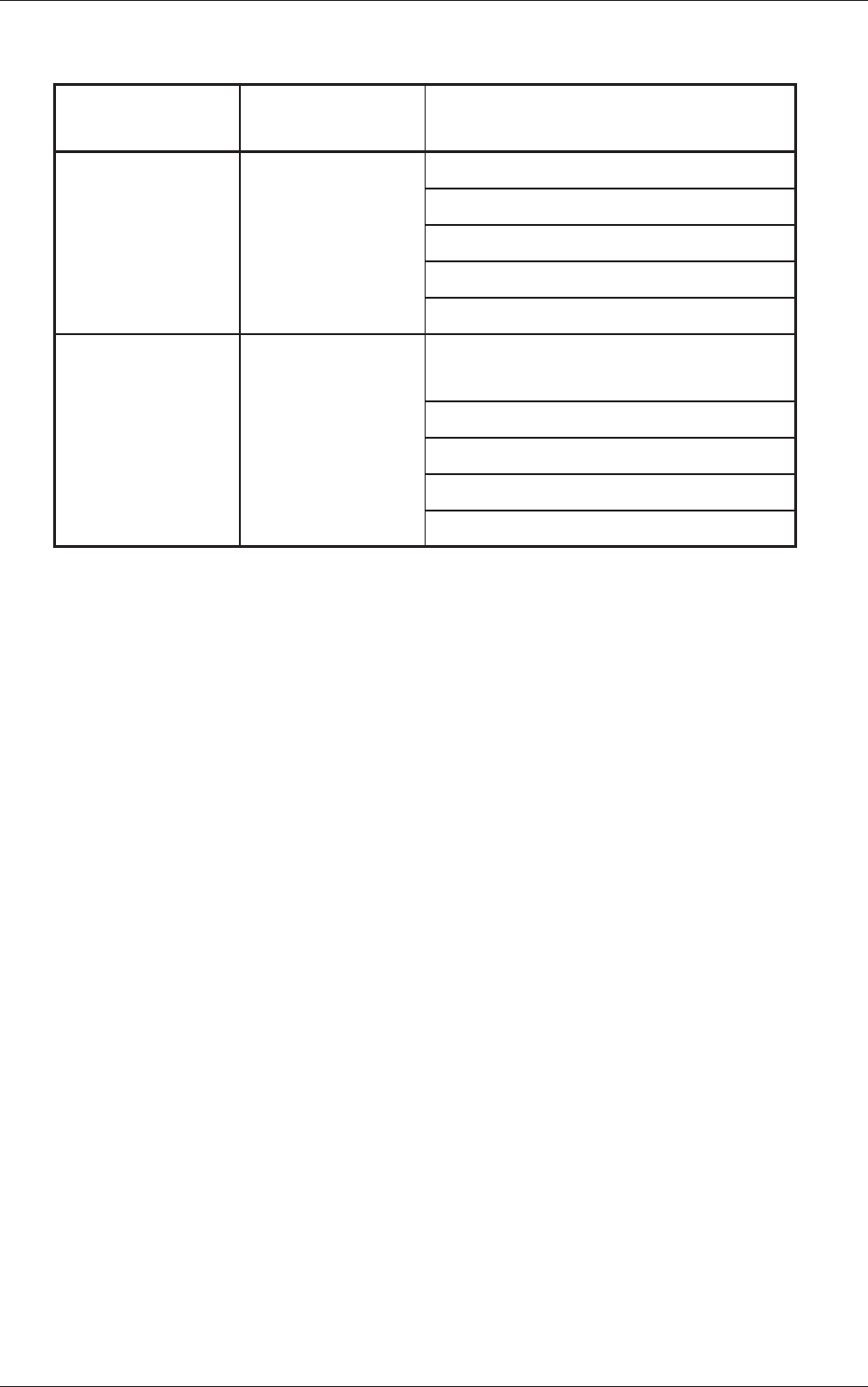
Failures can further be classifi ed as shown in the table below
.
Table 4E1
Classifi cation of
Failures
Contents of
Failures
Symptom of Failures
Failure before
Component
Placement
Component Pickup
Error
Components cannot be picked up.
Components are turned vertically.
A recognition error occurs.
Components fall down.
Others
Failure after
Component
Placement
Component
Placement Error
The positional and angular deviation of
component occurs.
Components are turned over and placed.
Some components are missing.
Some components are cracked or nicked.
Others
1.2 Helpful Hints on Countermeasures against Failure
•
The fi rst helpful hint on countermeasures against failure is to catch
precisely what kind of symptom is produced and how frequently the
symptom appears.
•
The second helpful hint is to grasp the tendency (environment and
condition) of a failure.
Shown below are the concrete items to be checked.
(1) Check if the failure occurs on specifi c components.
(2) Check if the failure occurs on a specifi c production lot.
(3) Check if the failure occurs on a specifi c machine.
(4) Check if the failure occurs at a limited stage.
•
The third helpful hint is to fi nd in which process the failure occurs.
In normal cases, a failure after component placement is found in the fi nal
inspection process. In such a case, it is required to track the failure by
checking all processes and specify the process in which the failure has
occurred.
It is very important to grasp a failure symptom precisely on these helpful
hints. Precise capture of a failure symptom makes it possible to track the
factor and make a plan to take countermeasures against the failure.
When this phenomenon grasp is negligently done, it takes time to defective
measures by executing ineffectual measures.
Especially, as for less failures (low generation rate), it is necessary to take
data accurately, examine the factors as a result, and execute measures
against such failures.
1.1 Classifi cation of Failure Symptoms
5-3
AKHEMT-ID
0605-001
2. Troubleshooting on Pickup Errors
2.1 Cause and Remedy of Pickup Errors
(1) Component-Based Factors
When the cause of a failure lies in specifi c components or lots, the
components must be examined fi rst of all.
Shown below are the cases of failures whose factors lie in components.
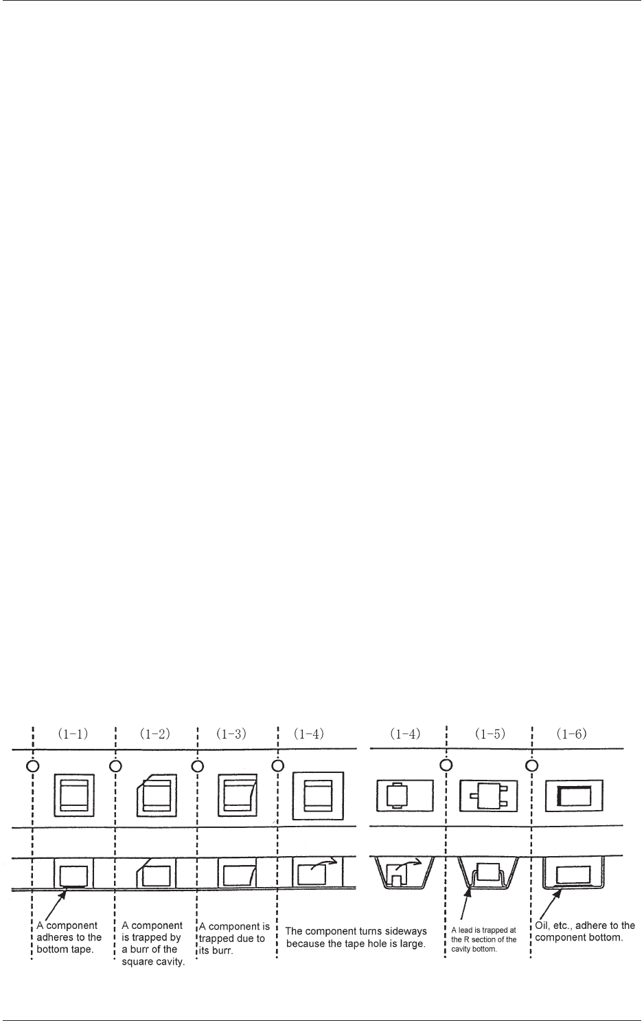
[Factors of Pickup Errors on Component Side]
(1-1) A component adheres to the bottom tape.
(1-2) The shape of a cavity is defective.
(1-3) The shape of a component is defective.
(1-4) A component turns sideways because the tape cavity is too large.
(1-5) The fl atness of the cavity bottom is defective.
(1-6) Oil or mold lubricant adheres to the bottom of a component.
The failures described in (1-1) through (1-4) have a tendency to occur
easily due to the components packaged in a paper tape and the failures
described in (1-4) through (1-6) due to the components packaged in an
embossed tape.
Special caution should be paid to minute components such as 0603 and
1005 types because such components are directly affected by how they
are packaged in the tape.
To determine whether or not the taped components are packaged in
good condition, turn the tape upside down and check to see how the
components fall down from the cavities. If the components fall down
freely, it means that they were packaged in good condition.
The specifi cations of taping are specifi ed in "JIS-C0806". However, as
the detailed regulations are not provided as for the failures described in
(1-1) through (1-6), it is required to ask the component maker about the
details when the components are purchased.
Fig. 4E2 Exemplifi cation of Troubled Taped Components
2. Troubleshooting on Pickup Errors