4H4CEOM2.pdf - 第19页
Page 7-13 DA T A MODIFICA TION 7 Chip Data / T ray Data 7-5-2 Extension Chip Data The pin information of the selected chip is checked and modified. 1 . Press Exten chip on the chip data screen. • The screen for the pin t…
Page 7-12
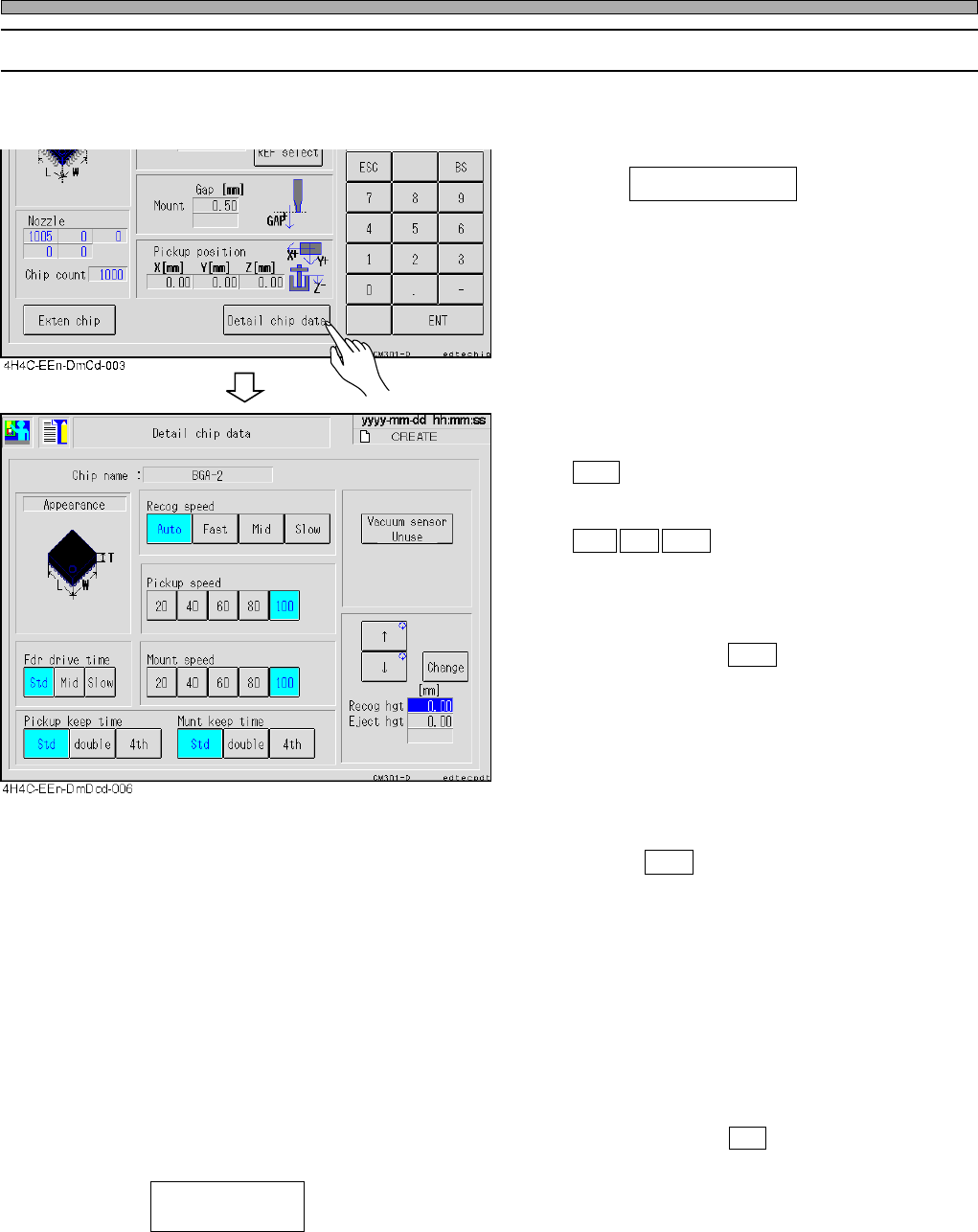
• Recog speed
Choose the scanning speed of chip recognition.
Auto :Judges the recognition speed automati-
cally through the chip size, REF, the
nozzle type, etc.
Fast Mid Slow :Performs recognition scan at
high/
middle/
low speed.
∗ Due to the machine’s property, the tact time at
Fast is not different from that at Mid, so do not
use Fast.
Normally, choose Auto .
• Pickup speed
Choose the Z-axis speed for pick-up.
• Fdr drive time
Choose the shutter feeding time of a feeder.
∗ If the machine is equipped with the optional
device that can feed the tape at low speed,
choose Slow at the target chip screen.
• Mount speed
Choose the X-, Y-, Z-, and θ-axis speed of until
mounting after pick-up.
• Pickup keep time/Munt keep time
For the pick-up keeping time/mount keeping
time (the stop time at the nozzle lowered
position) of the corresponding nozzle of the
nozzle library, select double (twofold), 4th
(fourfold) or Std (standard).
Normally, choose Std .
• -------Setting the parts pickup fault check by the vacuum sensor
Every time pressing, “Use” and “Without” will toggle.
• Recog hgt----------------The chip recognition height can be changed to the upper position than
usual. (0 mm - 21 mm)
• Eject hgt------------------The chip ejecting height can be changed to the upper position than usual.
(0 mm - 21 mm)
4H4C-E-OMA07-A01-05
Chip Data / Tray Data
7-5-1 Detail Chip Data
Such conditions of the recognition, pickup, and mounting for applicable chips as a recognition
speed or pickup maintaining time are checked and corrected.
1. Press Detail chip data on the chip
data screen.
Vacuum sensor
(Use / Without)
Page 7-13
DATA MODIFICATION
7
Chip Data / Tray Data
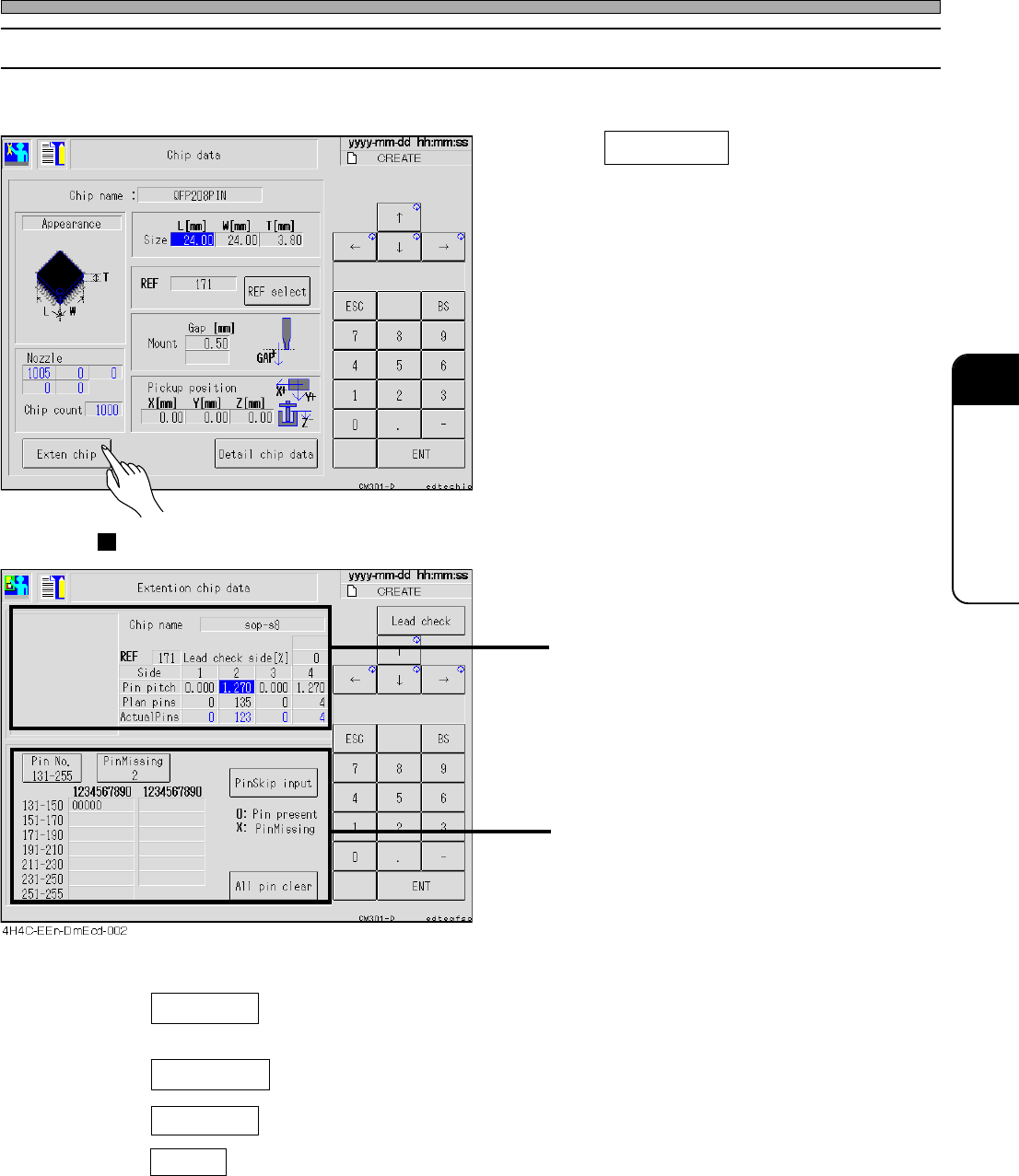
7-5-2 Extension Chip Data
The pin information of the selected chip is checked and modified.
1. Press Exten chip on the chip data
screen.
• The screen for the pin type chip (SOP, QFP,
etc.) and that for the ball type chip (BGA, CSP,
etc.) are displayed.
Pin Type (SOP, QFP, etc.)
Data of pin pitch and the number of pins for
each side including the description of the sides
Missing pin data for each side
• Pin Missing ---------- Select the side to display the missing pin data. (Every pressing of it
changes the side as 1, 2, 3, 4, and 1.)
• PinSkip input ---------- Selecting the pin number of the displayed side sets pin present and pin
missing in turn.
• All pin clear ---------- All data of missing pins of the displayed sides are cleared.
• Pin No. ---------- 1 - 30 and 131 - 255 are toggled.
4H4C-E-OMA07-A01-03
4H4C-EEn-DmCd-003
Page 7-14
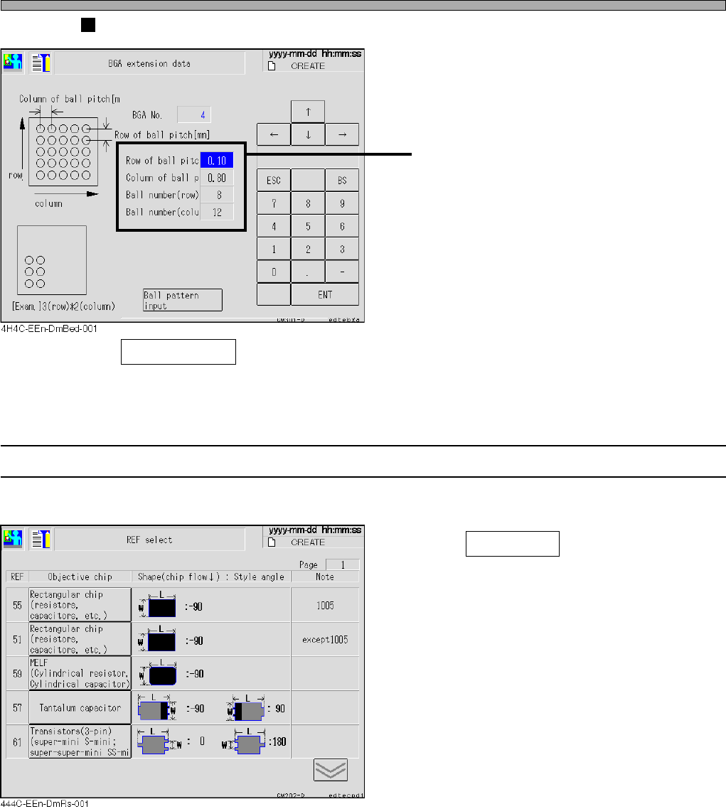
Ball Type (BGA, CSP, etc.)
Ball arrangement data
• Ball pattern input ----- Enter the ball arrangement pattern.
7-5-3 Selecting REF
The desired chip is selected.
1. Press REF select on the chip data
screen.
• Check the shape and select one from the chips
listed under the objective chip.
4H4C-E-OMA07-A01-02
Chip Data / Tray Data