4H4CEOM2.pdf - 第8页
Page 7-2 4H4C-E-OMA07-A01-01 7-1 Data Modification Menu Data modification menu 4H4C-004TE u n e M s t n e t n o C a t a d B C P . d e i f i d o m d n a d e k c e h c s i a t a d d r a o b e h T a t a d l a i c u d i F d …
Page 7-1
4H4C-E-OMA07-A01-03
Chapter 7
DATA MODIFICATION
Data Modification
Basically, this machine can modify data which requires the modification after teaching
and the coordinate data, and they are displayed in black.
Data only for checking is displayed in blue, and data must be modified on PT.
Modifiable data whose indicator is the switch enables the cursor to move to that data
by pressing the one for those data lightly.
∗
The meaning of each data is described in Programming Manual of PT in details.
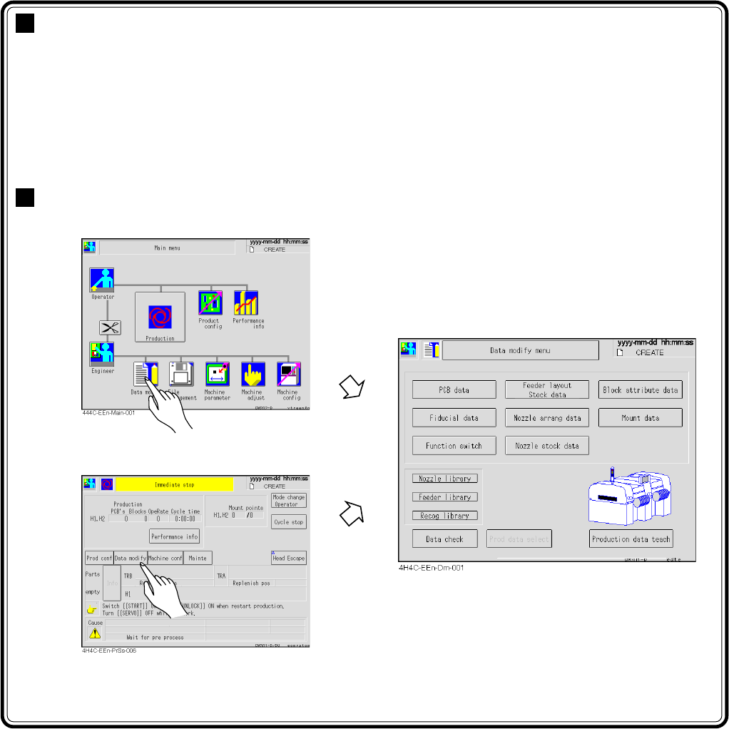
Entering Data Modification
∗ You can enter from the screen during
the production stop.
Page 7-2
4H4C-E-OMA07-A01-01
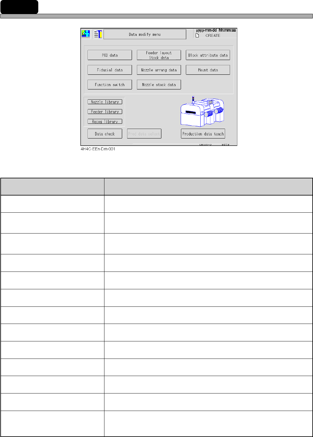
7-1 Data Modification Menu
Data modification menu
4H4C-004TE
uneM stnetnoC
atadBCP
.deifidomdnadekcehcsiataddraobehT
atadlaicudiF
draobehtnehW.deifidomdnadekcehcsiatadnoitingocerdraobehT
.tiretnetonnacuoy,ffodenrutsihctiwsnoitcnuffonoitingocer
atadkcotS/tuoyalredeeF
.rehtegotdeyalpsideraatadkcotsdnatuoyalredeefehT
.deifidomdnadekcehcsidesuebotatadpihcehT
atadgnarraelzzoN
.dekcehcsiatadtnemegnarraelzzonehT
atadkcotselzzoN
.dekcehcsiatadkcotselzzonehT
atadetubirttakcolB
.deifidomdnadekcehcsiatadetubirttakcolbehT
atadtnuoM
.deifidomdnadekcehcsiatadtnuomehT
hctiwsnoitcnuF
.dekcehcsinoitidnocgnitarepoehttesothctiwsnoitcnuffognittesehT
yrarbilelzzoN
.deyalpsidsielzzonehtfoatadyrarbilehT
yrarbilredeeF
.deyalpsidsiredeefepatehtfoatadyrarbilehT
yrarbilnoitingoceR
.deyalpsidsinoitingocerehtfoatadyrarbilehT
kcehcataD
.dekcehcsiatadnoitcudorpehT
hcaetatadnoitcudorP
noitcudorpehtfI(.yrassecenfidegnahcdna,thguatsiatadnoitcudorpehT
).tiretnetonnacuoy,dednetonsi
.gnihcaetrof”gnihcaeT8retpahC“otrefeR
Chapter 8 Teaching
Page 7-3
DATA MODIFICATION
7
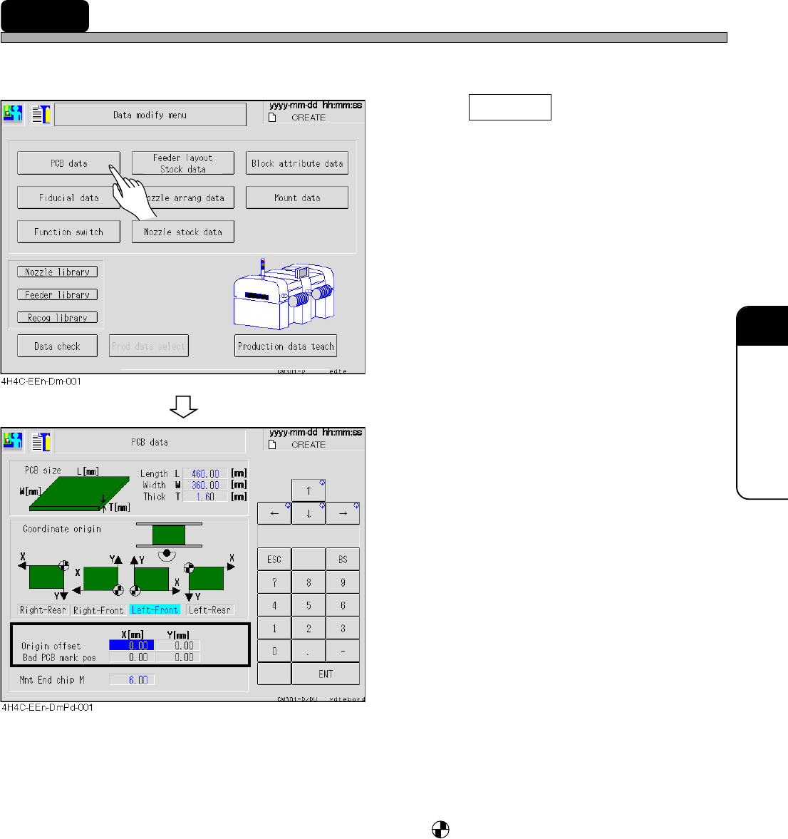
7-2 PCB Data
The PCB data is checked.
1. Press PCB data .
• The PCB data screen appears.
2. Modify data if necessary.
• Only data of the origin offset and the bad PCB
mark position can be modified.
• PCB size ------------------------------ L indicates the X direction of the mount data and W is that of the
Y direction.
• Coordinate origin ------------------ The origin mark, is the coordinate origin (0, 0) of the mount,
board recognition, and bad mark coordinates viewed from the
front of the machine.
• Origin offset ------------------------- The offset for whole board (mount, board recognition, and bad
mark coordinates).
• Bad PCB mark position --------- The mark position for marking the bad board mark.
For modification, set ON the bad PCB mark detection on PT by
the function switch.
4H4C-E-OMA07-A01-02