4H4CEOM2.pdf - 第57页
Page 8-29 TEACHING 8 4H4C-E-OMA08-A02-01 Chip Recognition T eaching Lamp V alue Offset 28. Press UNLOCK + T each start . 29. Perform the block match recognition steps 1. to 6. • Adjust lamp 3 (transmission), lamp 4 (refl…
Page 8-28
4H4C-E-OMA08-A02-02
Chip Recognition Teaching
23. Press
UNLOCK
+ Recognition .
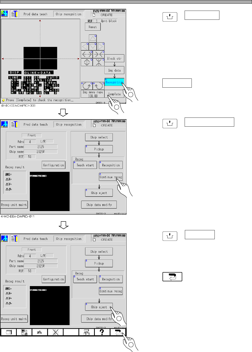
• The recognition result appears on the recogni-
tion screen.
∗ When the recognition result (ANS=) is under
the recognition rate (the judgment value ratio of
the machine parameter), carry out steps 7 to
24 and retry the recognition by changing
recognition points and so on.
24. Press Complete .
• Teaching is over.
25. Press
UNLOCK
+ Continuous recog for
checking.
• The recognition is continued 10 times, and the
result appears. After checking the result, press
“ESC” and close the displayed result.
(It is just for checking and unnecessary to
operate.)
∗ When the recognition result (ANS=) is under
the recognition ratio (the judgment value ratio
of the machine parameter), operate steps 7 to
24 and retry the recognition by changing the
recognition points and so on.
26. Press
UNLOCK
+ Chip eject .
• The chip used for recognition is ejected.
27. Press .
• 4-point block match recognition teaching is
over.
• At this time, the taught data are uploaded to
the PT.
4H4C-EEn-DmPtCr-011
2
2
1
1
Page 8-29
TEACHING
8
4H4C-E-OMA08-A02-01
Chip Recognition Teaching
Lamp Value Offset
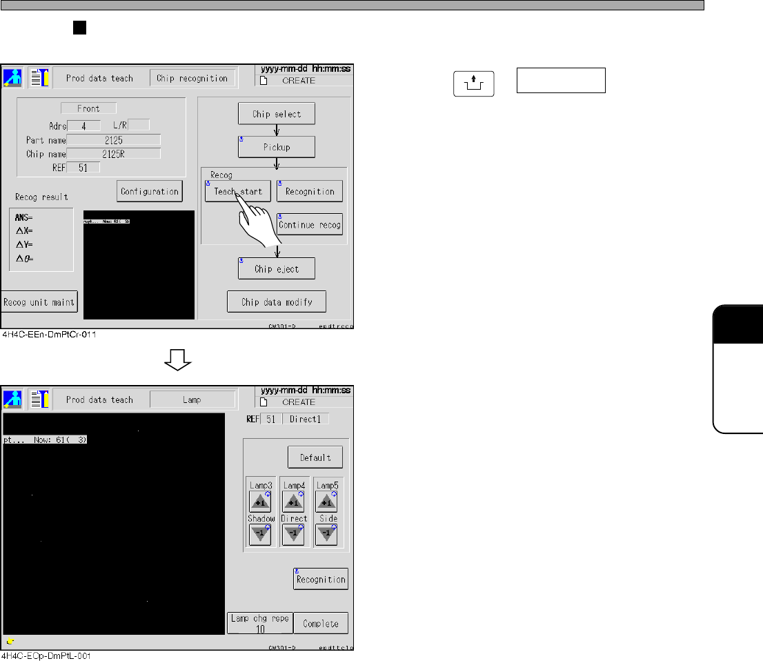
28. Press
UNLOCK
+ Teach start .
29. Perform the block match recognition
steps 1. to 6.
• Adjust lamp 3 (transmission), lamp 4 (reflec-
tion) and lamp 5 (BGA side lighting) by using +
and - buttons.
• After changing, actually perform recognition to
check.
• When the result is good, save it by pressing
Complete.
∗ If Complete is not pressed after adjusting lamp
values by using + and - buttons, the result will
not be reflected on the data.
∗ Depending on the lamp mode in the reference,
changeable lamp value will be decided.
Transmission --- Lamp 3 only
Reflection 1 ----- Lamp 4 only
Reflection 2 ----- Lamp 4 and 5
BGA--------------- Lamp 3, 4 and 5
Page 8-30
8-6 Teaching the Mount Position
8-6-1 Teaching the Mount Position
When the mount position on the same pattern of the production board deviates in succession, it
can be corrected by teaching the mount position.
Teaching the mount position has three kinds of teaching modes, use them depending on each
deviation.
1 Mount
When only the mount position of the specified sequence is deviated, use this. The mount data
coordinate of the taught sequence is changed.
2 Mount / block
When the mount position at the same position in each block is deviated, use this. All mount data
coordinates of the same block No. as taught chips, and applicable block data are changed.
3 Pattern
When the mount position is deviated as a whole, in spite of proper data for the board recognition,
use this. Change the origin offset and the board recognition coordinate, and use the changed
coordinate distance of taught chips for all chips.
NOTICE
Before using these teachings, ensure that the CAD data corresponds to the data
being used. These teachings are the same operation as changing CAD data, so
manage data properly after teaching.
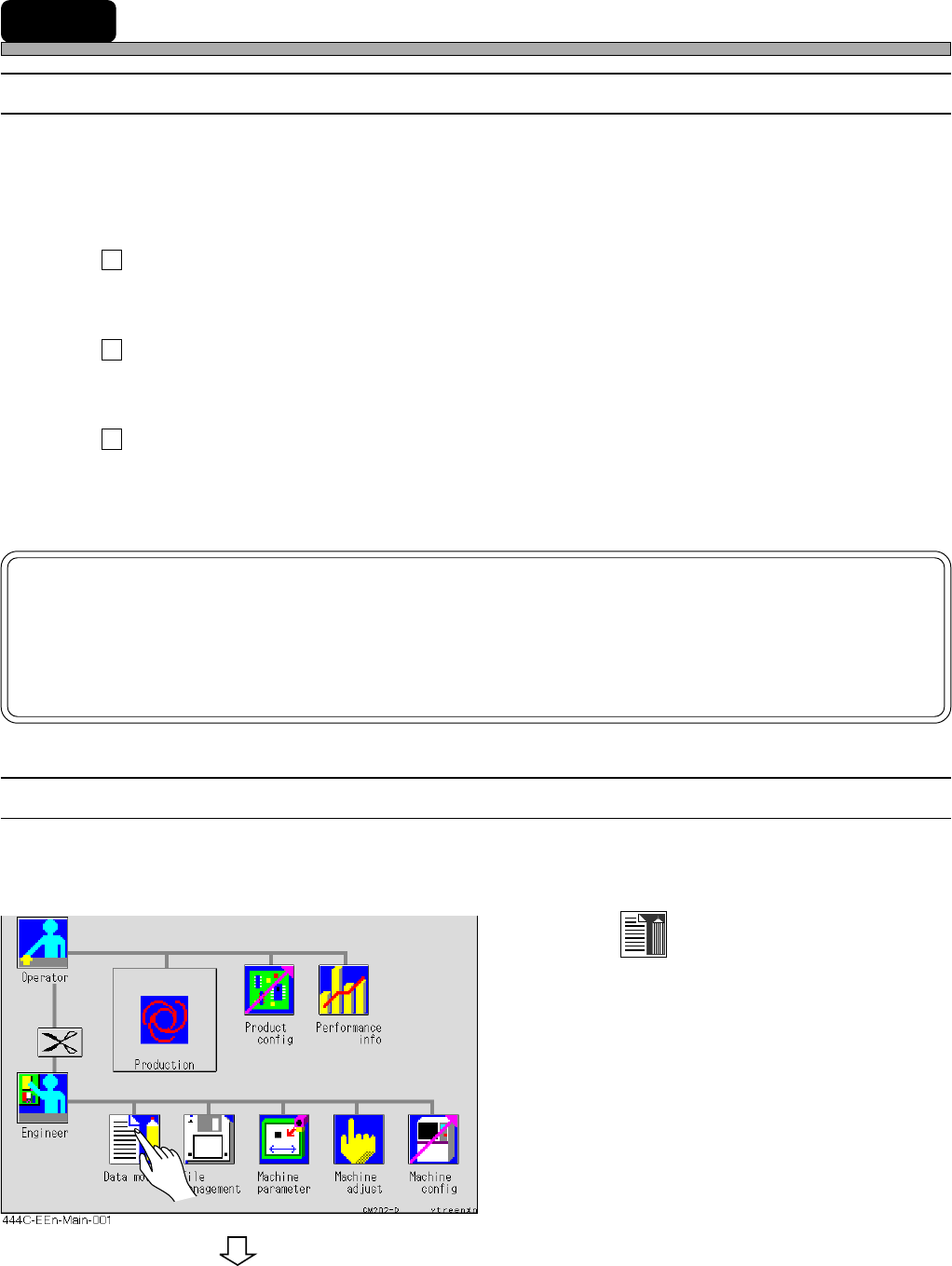
8-6-2 Creating Procedure
This section describes the representative procedure of the mount teaching.
1. Press
Data modify
.
• The data modification menu screen appears.
To the next page
4H4C-E-OMA08-A03-02