4H4CEOM2.pdf - 第98页
Page 10-8 = MEMO = 4H4C-E-OMA10-A01-02
Page 10-7
OPTION
10
Transport Speed Variable Adjustment
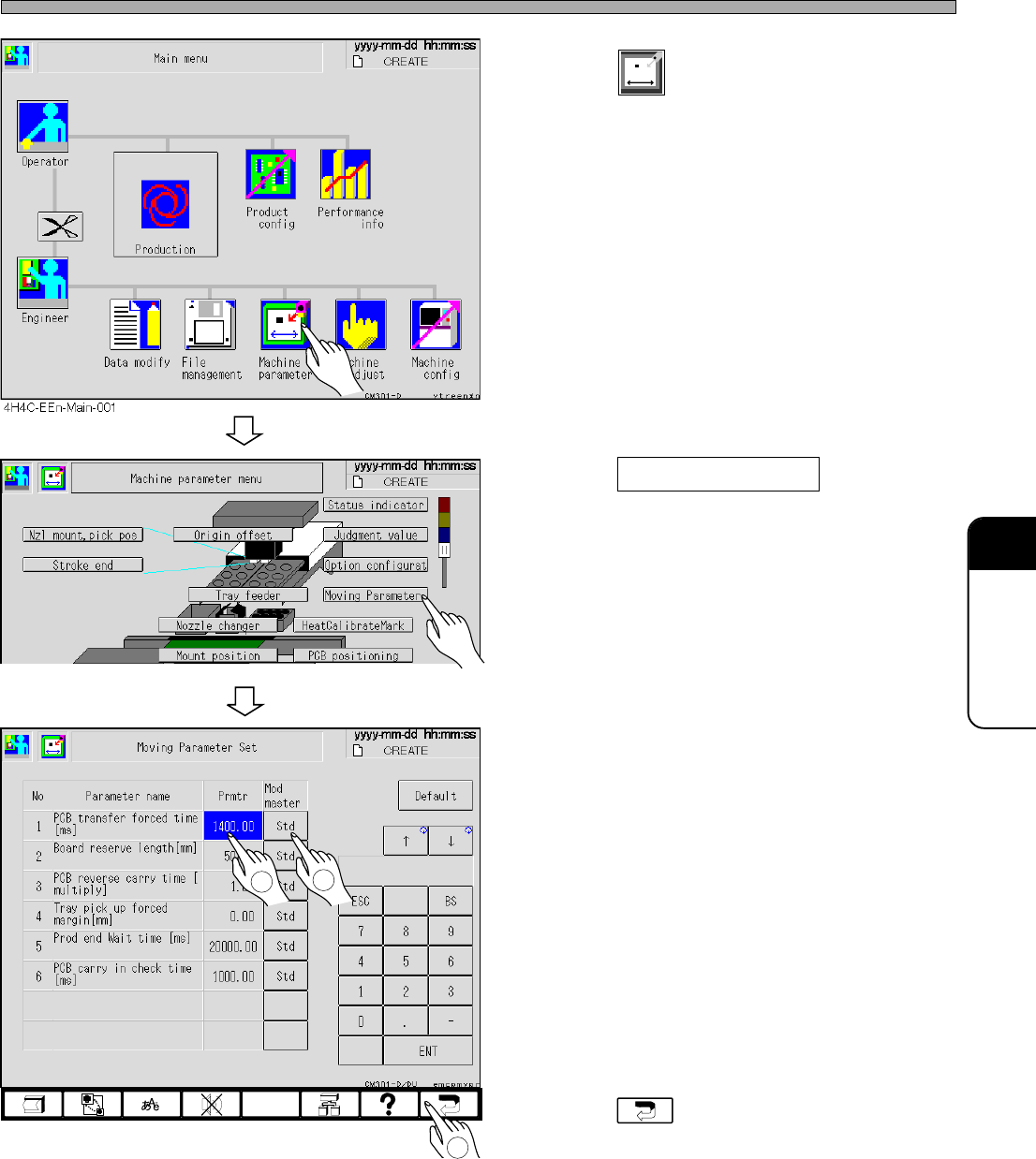
12. Press
Machine
parameter
.
• The machine parameters menu is displayed.
13. Press Moving Parameter .
• The “Moving Parameter Set” screen is dis-
played.
14. Set the board transport forced-in
time.
∗ Set the parameter value for 1500 ms or over.
15. Change the master change to “Spcl”.
• Whenever pressed, “Std” and “Spcl” toggles.
So select “Spcl”.
16. Return to the main menu.
∗ Press until the main menu is displayed.
∗ After the transport test, if the parameters need
setting again, repeat steps 11 to 15.
4H4C-E-OMA10-A01-04
4H4C-EEn-Mp-002
4H4C-EEn-MaMps-005
2
1
3

Page 10-8
= MEMO =
4H4C-E-OMA10-A01-02

Page 1
4H4C-E-OMA0Z-A01-03
D
Daily production ...............................................4-1
Data check .....................................................7-22
Data modification .............................................7-1
Data modification menu ...................................7-2
Date, time and data name display area ...........2-3
Deceleration Speed Adjustment.....................10-3
Defective head ...............................................3-28
Detail chip data ..............................................7-12
Display-changing switches...............................2-7
E
Emergency stop button ............................1-3, 2-2
Engineer mode...................2-10, 2-12, 3-3, 4-12
Entering data modification ...............................7-1
Equipment specification .................................1-14
Evolution data ..................................................7-6
Extension chip data........................................7-13
External view............................................1-2, 1-9
F
Feeder arrangement ........................................3-9
Feeder layout / stock data................................7-7
Feeder library.................................................7-20
Feeder table.....................................................1-2
File operation ...................................................6-1
File operation of the floppy disk .......................6-5
Finishing machine ..........................................4-13
Floppy disk drive ..............................................1-3
Front panel.......................................................1-2
Front safety cover ............................................1-2
Front side cover ...............................................1-2
Function keys...................................................2-4
Function switch ..............................................7-19
Functions..........................................................3-1
G
General description..........................................1-1
H
Handle for carry ...............................................1-9
Head camera ...................................................1-8
Head unit..........................................................1-5
Help..........................................................2-4, 2-5
Hierarchy, mode and menu name display area ...
2-3
How to clamp tray ............................................5-3
I
Immediate stop...............................................4-10
Information and functions during stop............4-12
Input check.....................................................3-24
Input switches ..................................................2-6
Symbols
3-color indicator light................................1-2, 1-4
A
Adjuster bolt for transport.................................1-9
Adjusting the transfer rail width........................9-4
All reset ..........................................................3-13
Angle definition ......................................3-10, 7-9
Arrow switches .................................................2-8
Automatic stop ...............................................4-13
Available board ..............................................1-17
Available feeders............................................1-18
Axis information .............................................3-26
B
Bad mark recognition .......................................8-9
Bad mark recognition teaching ........................8-9
Ball type .........................................................7-14
Basic operation ................................................2-1
Block attribute data ........................................7-17
Block match recognition.........................8-2, 8-23
Board conveyor................................................1-5
Board flowing direction...................................1-15
Board holder.....................................................1-7
Board recognition .............................................8-3
Board recognition data .....................................7-4
Board recognition teaching ..............................8-3
Board transfer test..........................................9-14
Board transport ......................................3-8, 3-21
Board transport forced time............................10-7
Bulk feeder.......................................................5-1
Buzzer stop ......................................................2-4
C
Calculating chip consumption ..........................3-6
Caster for installation .......................................1-9
Changing parts...............................................3-13
Changing support pins ...................................3-11
Changing the production board........................9-1
Changing the production data ..........................9-2
Checking air pressure ......................................4-4
Checking the nozzle arrangement ...................9-9
Chip data........................................................7-10
Chip feeding devices........................................5-1
Chip recognition .............................................8-18
Chip recognition teaching ..............................8-18
Chip supply area ..............................................1-9
Complete part information................................7-9
Completion of production ...............................4-13
Comprehensive parts information ..................3-10
Conditional mount ..........................................9-16
Conveyor width adjustment............................3-21
Copyright, system version and screen name display area ...
2-3
Coupling settlement knob ................................1-9
Customizing operator mode...........................3-30
Cycle stop ......................................................4-11