4H4CEOM2.pdf - 第53页
Page 8-25 TEACHING 8 4H4C-E-OMA08-A02-02 Chip Recognition T eaching 9. Correct the angle of the chip which is picked up, and move the chip to the center of the recognition screen. • Move with . 10. Put the outline of the…
Page 8-24
Chip Recognition Teaching
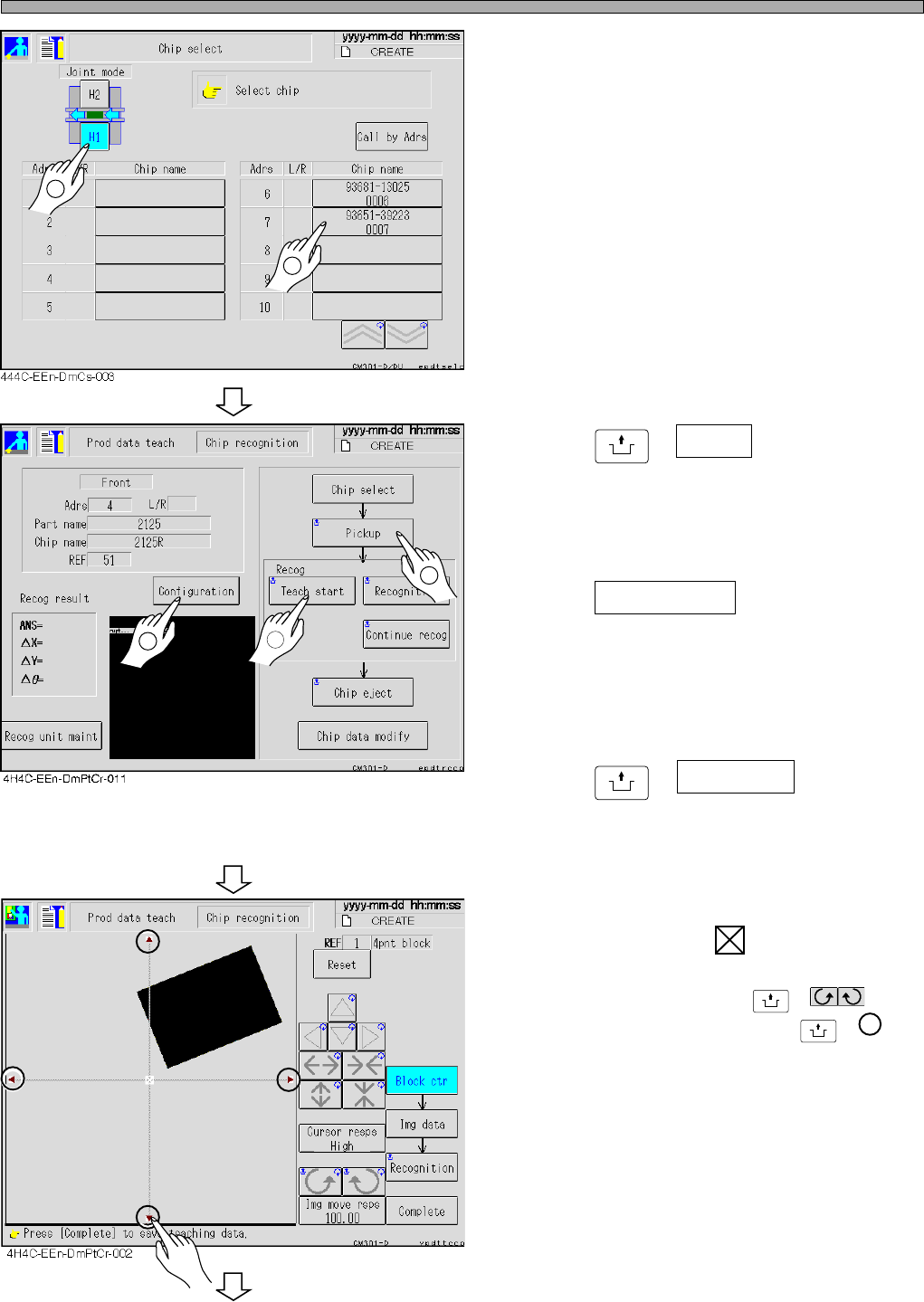
4. Select the chip to be recognized.
∗ After selecting the feeder table press the chip
name for teaching.
5. Press
UNLOCK
+ Pickup .
• The chip is picked up and moved to the chip
recognition position.
• Set the teaching type after selecting a chip.
6. Press Configuration .
• When “Recognition” is displayed above the
teaching start switch, block match teaching is
performed. When “Lamp” is displayed there,
lamp value offset teaching is performed.
7. Press
UNLOCK
+ Teach start .
• The recognition screen is enlarged, and
teaching starts.
8. Overlap the pickup position of the
chip to the center of the block.
• The angle is corrected by
UNLOCK
+ , and
the image of the chip moves by
UNLOCK
+ .
∗ If the center of the parts does not match the
pickup position, set so that the pickup position
comes to the block center.
To the next page
1
2
4H4C-E-OMA08-A02-03
2
1
3
Page 8-25
TEACHING
8
4H4C-E-OMA08-A02-02
Chip Recognition Teaching
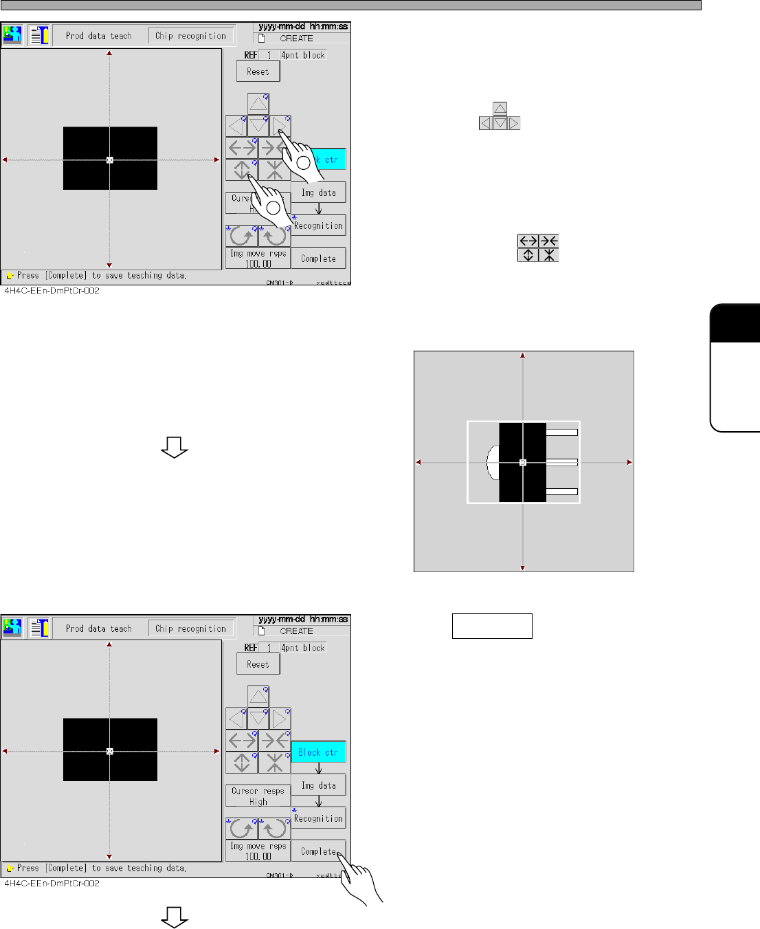
9. Correct the angle of the chip which is
picked up, and move the chip to the
center of the recognition screen.
• Move with .
10. Put the outline of the chip in the
frame of the block.
• Set the size with .
∗ For the chip with a pin, set so that the outline
including the center (pickup) position and the
pins is within the frame. (e.g. See the figure
below)
11. Press Complete .
• Teaching for each block starts.
To the next page
1
2
3Y3C-014P
Page 8-26
4H4C-E-OMA08-A02-02
Chip Recognition Teaching
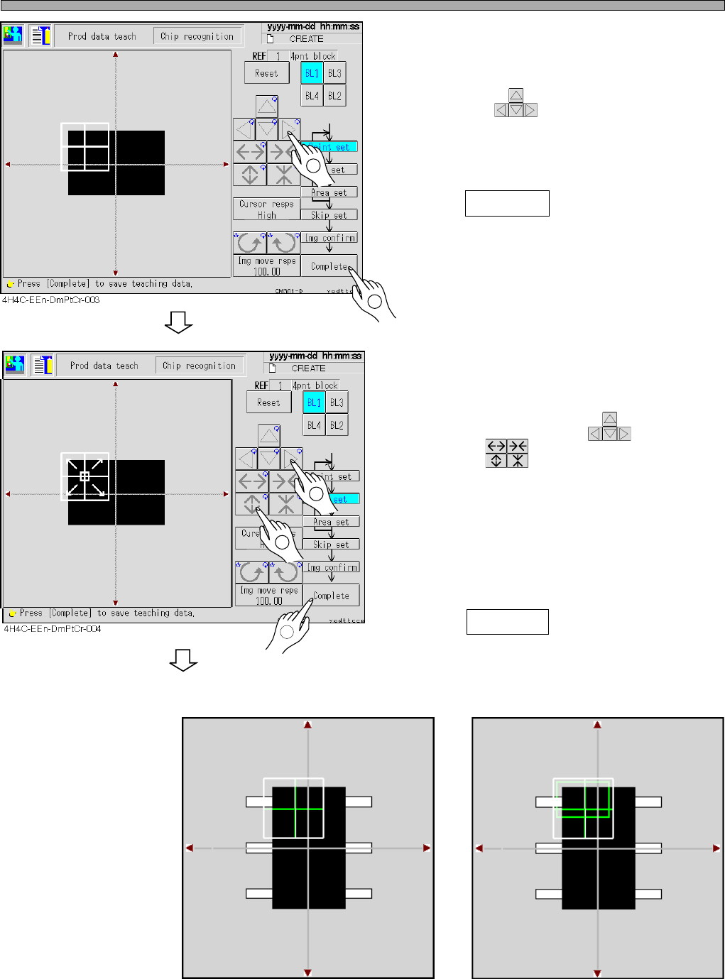
12. Set the point to be recognized by BL
1.
• Move with .
Set so that the chip (looks black) in the point
obtains about 70 % of the whole.
13. Press Complete .
∗ For the chip with the pins, also set so that the
chip which looks black obtains about 70% of
the whole. (e.g.: Recognition screen 1)
14. Set the range of the image to be rec-
ognized by BL 1.
• Move the inner frame appeared at the center of
the recognition point with , and set the
size with .
∗ Usually, set the recognition point at full size.
∗ For the chips with the pins or ones having
variations, set the range of the image to
recognize particular or stable points. (e.g.:
Recognition screen 2)
15. Press Complete .
Recognition screen 1 Recognition screen 2
3Y3C-015P
To the next page
1
2
1
2
3
Point
Chip
3Y3C-016P