OM-1743-005w.pdf - 第107页
1209-001 7.5.1.2 Left Side Cover #1 Attachment Procedure Procedure (1) Hold the left side of the Left Side Cover #1 and slide it in the arrow direction to attach. Insert the claw section on the Left Side Cover #1 into th…
7.5 Maintenance Method
7.5.1 Cover Removal and Attachment
7.5.1.1 Left Side Cover #1 Removal Procedure
Procedure
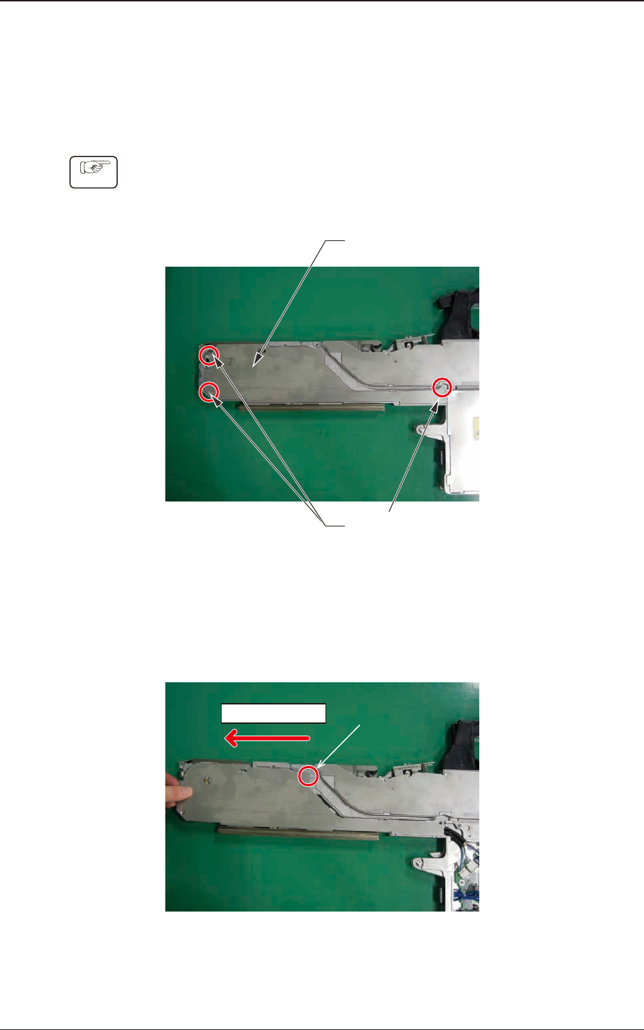
(1) Remove the three set screws for the Left Side Cover #1.
Cover Set Screws
Left Side Cover #1
Fig. G12
(2) Hold the left side of the Left Side Cover #1 and slide it in the arrow direction
to remove.
It is easier to remove the cover by raising the part A and sliding the cover.
Sliding Direction
A
Fig. G13
1209-001
7.5 Maintenance Method
OM-1743
7-12
1209-001
7.5.1.2 Left Side Cover #1 Attachment Procedure
Procedure
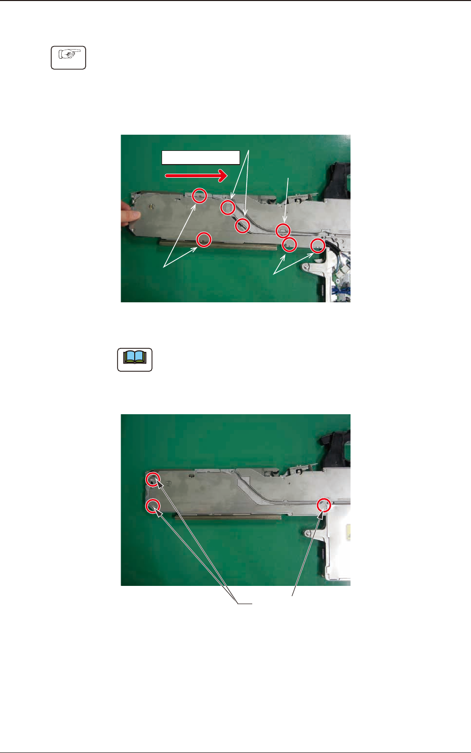
(1) Hold the left side of the Left Side Cover #1 and slide it in the arrow direction
to attach.
Insert the claw section on the Left Side Cover #1 into the slit with the
sequence of 1, 2, 3 and 4 shown in the gure below and slide the cover while
pressing it from above.
Sliding Direction
Step 1, 2 psitions
Step 2, 2 psitions
Step 4, 2 psitions
Step 1, 1 psition
Fig. G14
Note
When the cover is attached, take care not to catch any cable.
(2) Fasten the cover set screws and x the Left Side Cover #1.
Cover Set Screws
Fig. G15
7.5 Maintenance Method
OM-1743
7-13
1209-001
7.5.1.3 Left Side Cover #2 Removal Procedure
Procedure
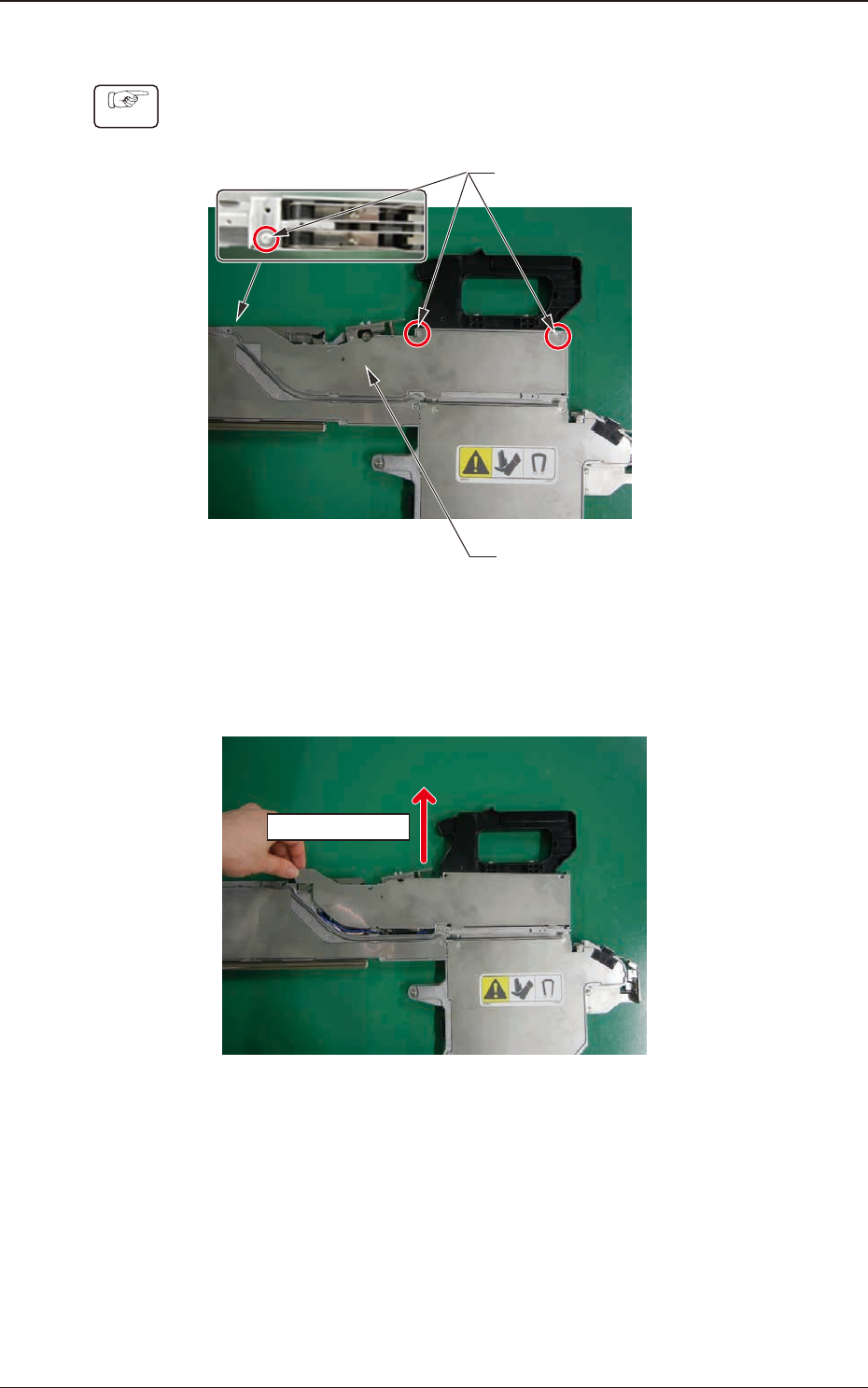
(1) Remove the three set screws for the Left Side Cover #2.
Left Side Cover #2
Cover Set Screws
Fig. G16
(2) Hold the upper side of the Left Side Cover #2 and slide it in the arrow
direction to remove.
Sliding Direction
Fig. G17
7.5 Maintenance Method
OM-1743
7-14