OM-1743-005w.pdf - 第114页
1209-001 7.5.1.8 Right Side Cover Attachment Procedure Procedure (1) Hold the upper side of the Right Side Cover and slide it in the arrow direction to attach. Insert the claw section on the Right Side Cover into the sli…
1209-001
7.5.1.7 Right Side Cover Removal Procedure
Procedure
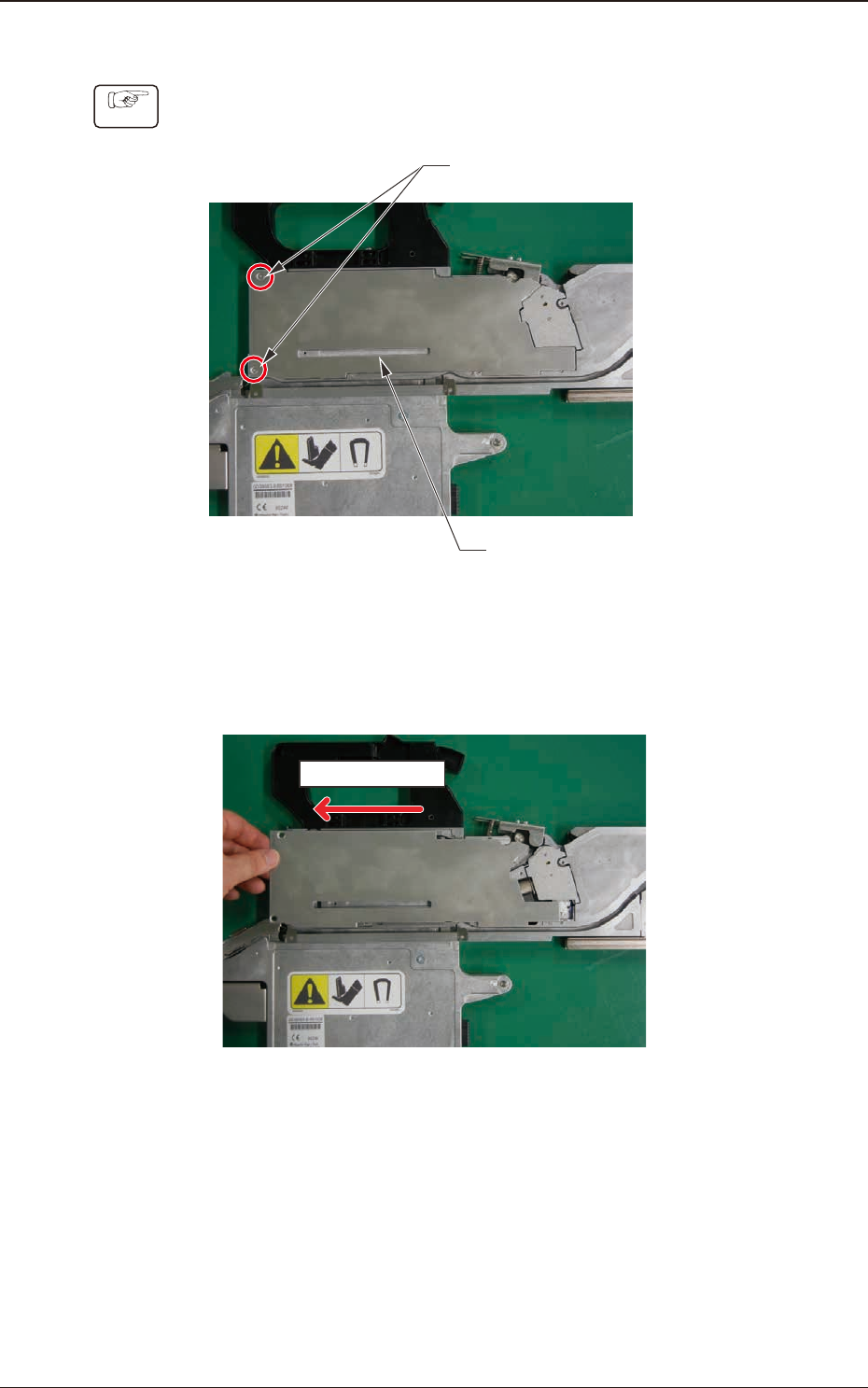
(1) Remove the two set screws for the Right Side Cover.
Right Side Cover #1
Cover Set Screws
Fig. G25
(2) Hold the left side of the Right Side Cover and slide it in the arrow direction
to remove.
Sliding Direction
Fig. G26
7.5 Maintenance Method
OM-1743
7-19
1209-001
7.5.1.8 Right Side Cover Attachment Procedure
Procedure
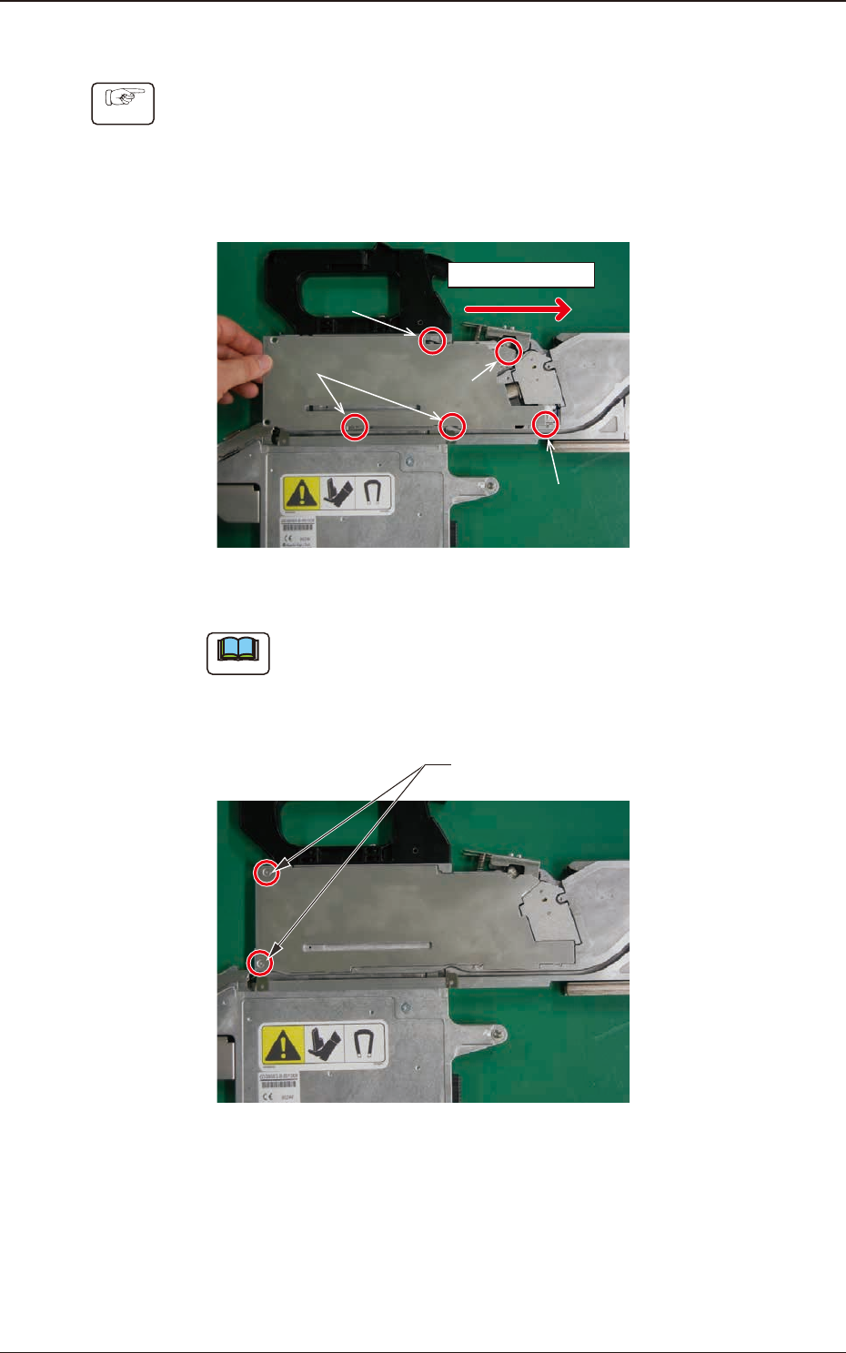
(1) Hold the upper side of the Right Side Cover and slide it in the arrow
direction to attach.
Insert the claw section on the Right Side Cover into the slit with the sequence
of 1, 2, 3 and 4 shown in the gure below and slide the cover while pressing
it from above.
Sliding Direction
Step 2
Step 3
Step 4
Step 1
Fig. G27
Note
When the cover is attached, take care not to catch any cable.
(2) Fasten the cover set screws to x the Right Side Cover.
Cover Set Screws
Fig. G28
7.5 Maintenance Method
OM-1743
7-20
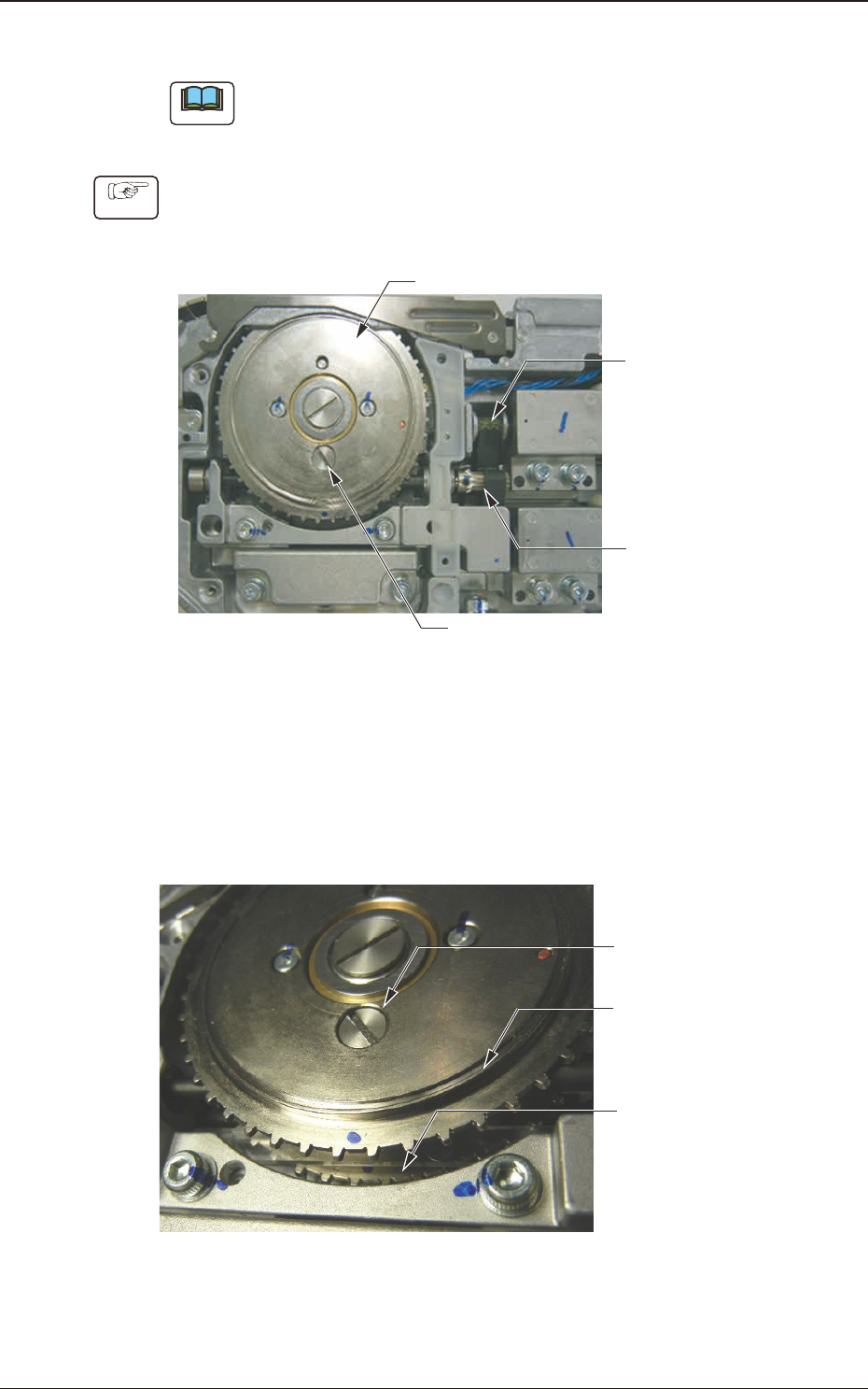
7.5.2 How to Apply Grease to the Sprocket Driving Gear Unit
Note
(a) Do not remove the timing belt.
(b) Do not apply grease onto the timing belt.
Procedure
(1) Opening the Left Side Cover (Refer to the item for the cover opening for the
procedure).
Open the Left Cover to expose the sprocket unit.
Sprocket Unit
Right
Timing
Pulley
Left
Timing
Pulley
Oiling Cap
Fig. G29
(2) Aligning the left sprocket position
Align the blue marked position on the sprocket rim with the lowermost
position.
Tun the left timing pulley so that the oiling cap locates the lowermost of the
left sprocket.
Right
Sprocket
Left
Sprocket
Oiling Cap
Fig. G30A
1901-005
7.5 Maintenance Method
OM-1743
7-21