OM-1743-005w.pdf - 第139页
1209-001 OM-1743 10-4
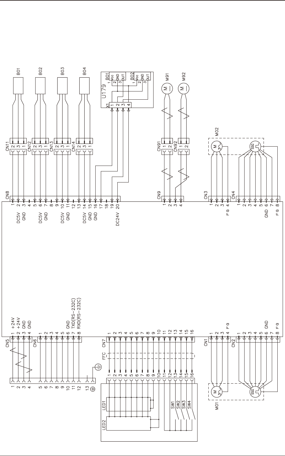
10.3 Feeder Control Circuit Diagram (GD-38083)
1209-001 -(M926WM---0001)
Drawer Connector
Lane 1 Servo Motor
Operation Panel
Lane 1 Feed Command
Lane 2 Feed Command
READY Signal
Connection Confirmation Signal
Connection Confirmation Signal
7-Segment LED is turned ON (a)
7-Segment LED is turned ON (b)
7-Segment LED is turned ON (c)
7-Segment LED is turned ON (d)
7-Segment LED is turned ON (e)
7-Segment LED is turned ON (f)
7-Segment LED is turned ON (g)
7-Segment LED is turned ON (D.P)
For Dynamic Light ON (first figure)
For Dynamic Light ON (second figure)
Cover Tape Take-up Key
Lane Selection Key
Forward Key
Backward Key
GND
GND
Motor Phase 1W
Motor Phase 1U
Motor Phase 1V
Encoder Phase 1A
/Encoder Phase 1A
Encoder Phase 1B
Power Supply (DC5V)
/Encoder Phase 1B
Feeder Control Amplifier
Lane 1 Joint Detection Sensor
Lane 2 Joint Detection Sensor
Lane 1 Tension Detection Sensor
Lane 2 Tension Detection Sensor
Lane 2 Sprocket Home Position
Detection Sensor
Lane 1 Sprocket Home Position
Detection Sensor
DC Motor 1
DC Motor 1 Power Supply
DC Motor 2
DC Motor 2 Power Supply
Motor Phase 2W
Motor Phase 2U
Motor Phase 2V
Encoder Phase 2A
/Encoder Phase 2A
Encoder Phase 2B
Power Supply (DC5V)
/Encoder Phase 2B
Reserve
Reserve
White
Brown
Blue
White
Brown
Blue
White
Brown
Blue
White
Brown
Blue
Blue
Black
Blue
Blue
Black
Blue
Blue
Black
Blue
Blue
Black
Blue
Blue
Black
Blue
Blue
Blue
Black
Blue
Black
Blue
Black
Blue
Black
Lane 2 Servo Motor
Lane 1 Take-up Motor
Lane 2 Take-up Motor
10.3 Feeder Control Circuit Diagram (GD-38083)
OM-1743
10-3

1209-001
OM-1743
10-4
11. Troubleshooting
The main troubleshooting during the tape feeder operation is described here.
In the event of trouble, con rm in which section the trouble is caused and set it
right.
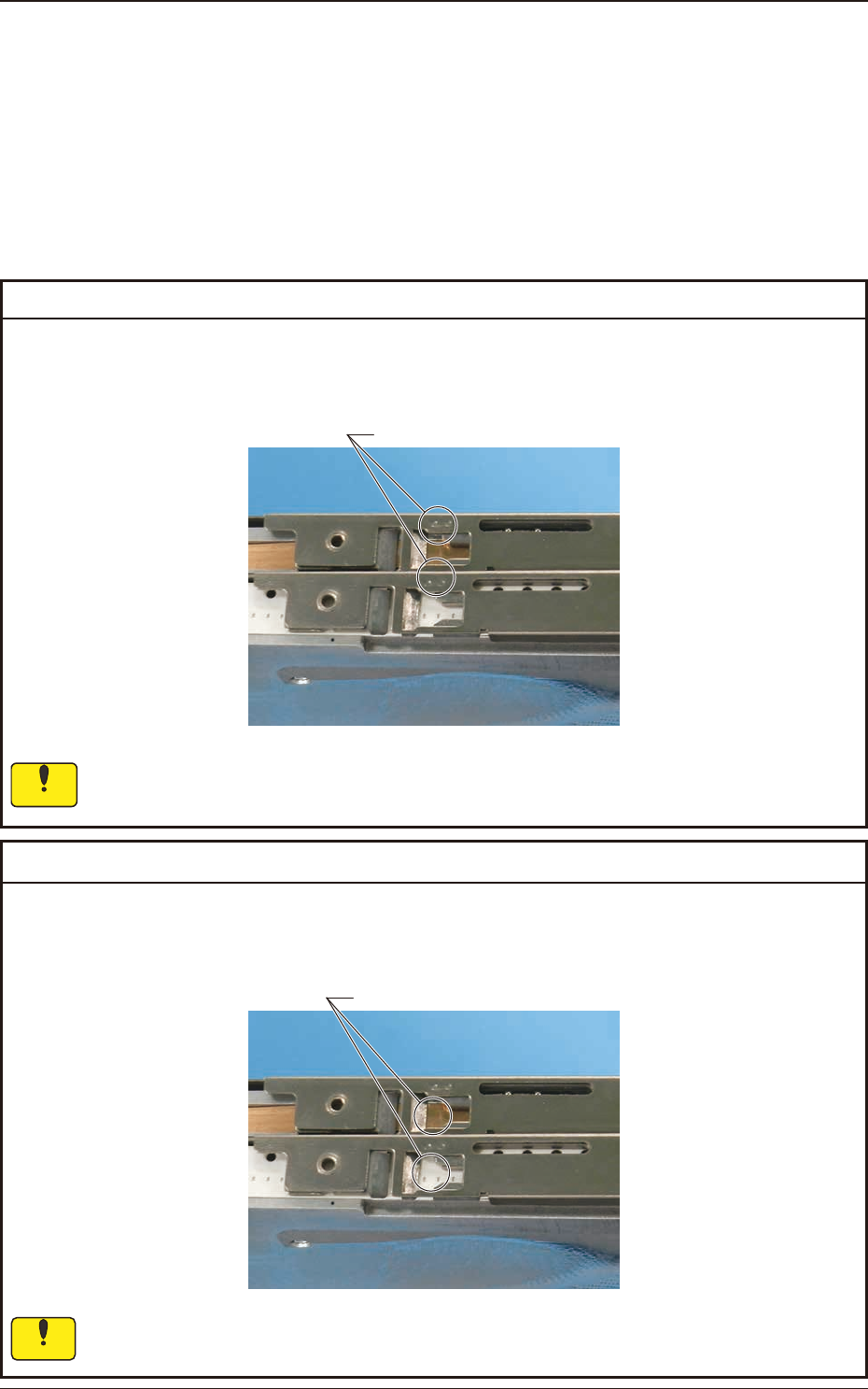
11.1 Component Pick-up Error
Remedy
: Align the chip component center with the marks on the suppressor according to "5.
Component Pick-up Position Alignment".
Marks on the Suppressor
If the component center is not aligned with the pick-up position, then the pick-up cannot
proceed correctly.
Cause : Inappropriate pick-up positioning
Notice
Remedy
: Adjust the pick-up position by using the feeder adjusting jig JG-0209
(Purchase separately).
Pick-up Position
If the component center is not aligned with the pick-up position, then the pick-up cannot
proceed correctly.
Cause : Error in Pick-up Position
1209-001
11. Troubleshooting
Notice
OM-1743
11-1