OM-1743-005w.pdf - 第50页
2.6.2 How to attach the Magnetic Plate Procedure (1) Loosen the set screw (round head screw) to remove the magnetic plate, and attach the magnetic plate onto the chute section. Notice (a) Conrm that there is no alien su…
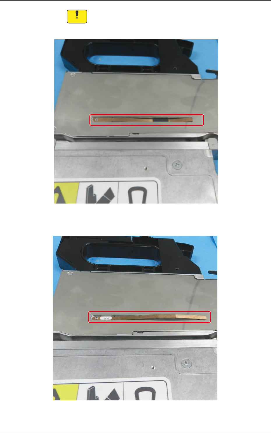
Notice
House the magnetic plate paying attention to its front and rear, so
that the magnetic plate does not stick out from the cover, as shown
in Fig. B24.
Correct:
The magnetic plate is housed under the cover.
Incorrect:
The magnetic plate sticks out of the cover.
Fig. B24
1209-001
2.6 Handling of Magnet Plate
OM-1743
2-19
2.6.2 How to attach the Magnetic Plate
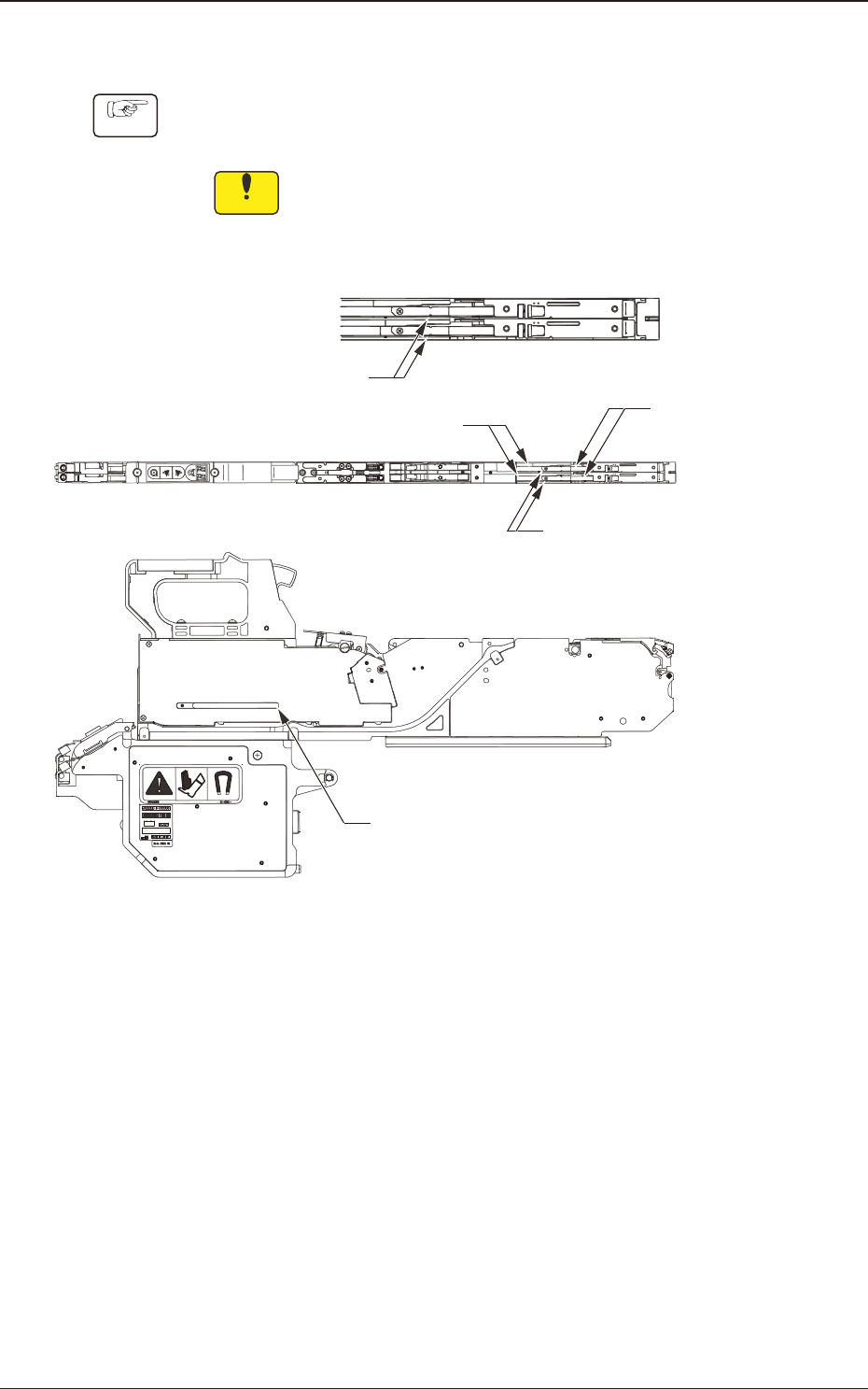
Procedure
(1) Loosen the set screw (round head screw) to remove the magnetic plate, and
attach the magnetic plate onto the chute section.
Notice
(a) Conrm that there is no alien substance in the chute groove.
(b) Insert the plate with the thickness of 0.1 to 0.5 mm (thickness
gauge or paper) between the chute wall and magnetic plate.
Then, tighten the set screw.
Set Screw
(Round Head Screw)
Magnetic Plate
Magnetic Plate housing section
Chute Section
Thickness of 0.1 to 0.5 mm
(thickness gauge or paper)
Fig. B25
1209-001
2.6 Handling of Magnet Plate
OM-1743
2-20
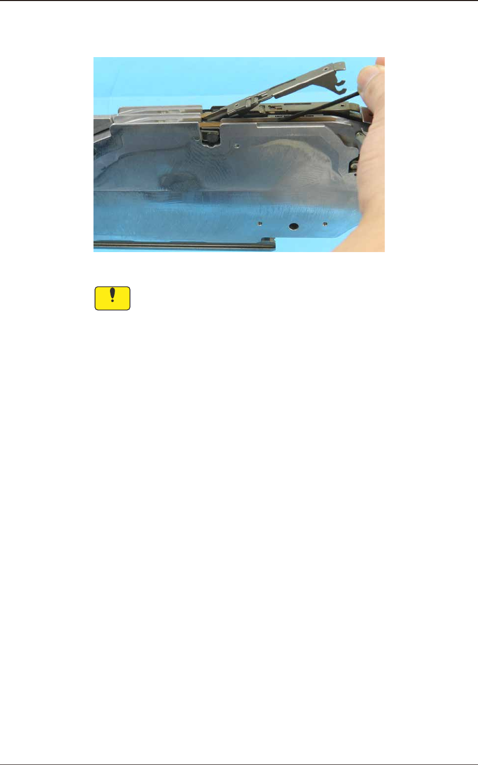
(2) After xing, press the Magnetic Plate down and make sure that it can be
returned smoothly when the nger is released from the Magnetic Plate.
Fig. B26
Notice
(a) If the Magnetic Plate is not moved up and down smoothly, the
component condition stabilization effect would be degraded.
When the magnetic plate is not moved up and down smoothly,
remove and re-install the magnetic plate.
(b) If the Magnetic Plate is deformed, the component condition
stabilization effect would be degraded.
Take greatest care not to deform the Magnetic Plate.
1209-001
2.6 Handling of Magnet Plate
OM-1743
2-21