OM-1743-005w.pdf - 第126页
8. Specications of T ape Feeders 8.1 Specications of 8 mm Dual T ape Feeder T able H1 Model T ape Width × Feed Pitch (mm) T ypes of T ape Standard Set Reel Outer Diameter × Width (mm) Chute Height (mm) Referential Comp…
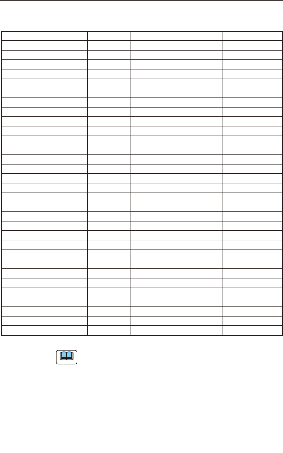
GD-38083 Maintenance Component List
Table G7A
Component Name PART No. PART NAME Q'ty
Recommended
Years
Worm Wheel ASSY (L) KYD-MC112-00 ASSY,GEAR (L) 1 3 years / 30 million feeds
Worm Wheel ASSY (R) KYD-MC113-00 ASSY,GEAR (R) 1 3 years / 30 million feeds
Take-up Worm Wheel KYD-MC131-00 GEAR(HASUBA) 2 3 years / 20 million feeds
Take-up Worm Motor KYD-MC11S-00 MOTOR_DC 2 3 years / 16 million feeds
Timing Belt KYD-MC13V-00 BELT_TIMING 2 4 years / 40 million feeds
Take-up Gear (Flat End Wheel 1) KYD-MC130-00 GEAR(HIRA-1) 2 4 years / 20 million feeds
Take-up Gear (Flat End Wheel 2) KYD-MC12L-00 GEAR(HIRA-2) 2 4 years / 20 million feeds
Sprocket ASSY (L) KYD-MC12G-00 ASSY_SPROCKET (L) 1 -
Sprocket ASSY (R) KYD-MC12H-00 ASSY_SPROCKET (R) 1 -
Cover (LA) KYD-MC10H-00 COVER (LA) 1 -
Cover (LB) KYD-MC10K-00 COVER (LB) 1 -
Cover (RB) KYD-MC10L-00 COVER (RB) 1 -
Cover (KIBAN) KYD-MC10J-00 COVER (KIBAN) 1 -
Front End Guide KYD-MC13H-00 GUIDE 1 -
Front Hook KYD-MC10T-00 ASSY_HOOK 2 -
Front Hook Spring KYD-MC12P-00 SPRING_COMP(F) 2 -
Suppressor ASSY (GD-38083) KYD-MC10S-00 ASSY_LEVER (GD-38083) 2 -
Suppressor Lock Spring KYD-MC12A-00 SPRING_COMP(SUP) 2 -
Magnetic Plate KYD-MC114-00
ASSY_PLATE (MAG)
2 -
Tension Lever ASSY (L) KYD-MC12J-00
ASSY_TENSION(L)
1 -
Tension Lever ASSY (R) KYD-MC12K-00
ASSY_TENSION(R)
1 -
Roll-in Preventive Plate KYD-MC11X-00
COVER
2 -
Scraper (L) KYD-MC13F-00
BLOCK(L)
1 -
Scraper (R) KYD-MC13G-00
BLOCK(R)
1 -
Take-up Cancel Lever (L) KYD-MC118-00
ASSY_LEVER(L)
1 -
Take-up Cancel Lever (R) KYD-MC119-00
ASSY_LEVER(R)
1 -
Conductive Grip KYD-MC125-00 ASSY_GRIP 1 -
Conductive Grip Cover KYD-MC11W-00 COVER(GRIP) 1 -
Operation Panel KYD-MC121-00 PCB_MOUNT 1 -
Cover Tape Outlet Cover KYD-MC12N-00 COVER(FUTA) 1 -
Cutter KYD-MC13X-00 CUTTER 1 -
Note
(a) The numbers entitled "Recommended Years" indicate the referential values
with 4 mm feed pitch.
Replacement may be required depending on the *actual use or maintenance
status regardless of the recommended years or specied feed amount.
*When picking up components continuously with one feeder
(b) Because the cutter blade is very sharp, when the cutter is to be changed, do
not hold the blade section. Take the greatest care not to get injured.
1901-005
7.6 Maintenance Component List
OM-1743
7-31
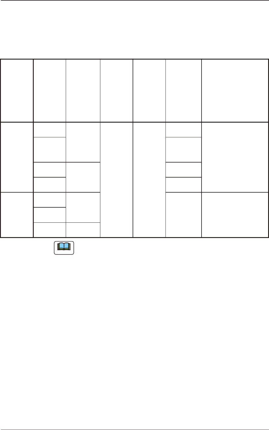
8. Specications of Tape Feeders
8.1 Specications of 8 mm Dual Tape Feeder
Table H1
Model
Tape
Width
×
Feed
Pitch
(mm)
Types of
Tape
Standard
Set
Reel
Outer
Diameter
×
Width
(mm)
Chute
Height
(mm)
Referential
Components
Remarks
GT-38080
GD-38080
8×2
Paper
φ
178 to
382
×
14.4
104.0
1005
•
Barcode Label Color
: White
8×4
2012
3216
3225
8×2
Embossed
8×4
GD-38083
8×1
Paper
0402
0603
1005
•
Barcode Label Color
: Blue + White
•
Applicable to 1 mm
pitch tape
8×2
8×2 Embossed
Note
The sizes of the components entitled "Referential Components" differ depending
on the component makers.
The components are shown as types for your reference.
1209-001
8. Specications of Tape Feeders
OM-1743
8-1
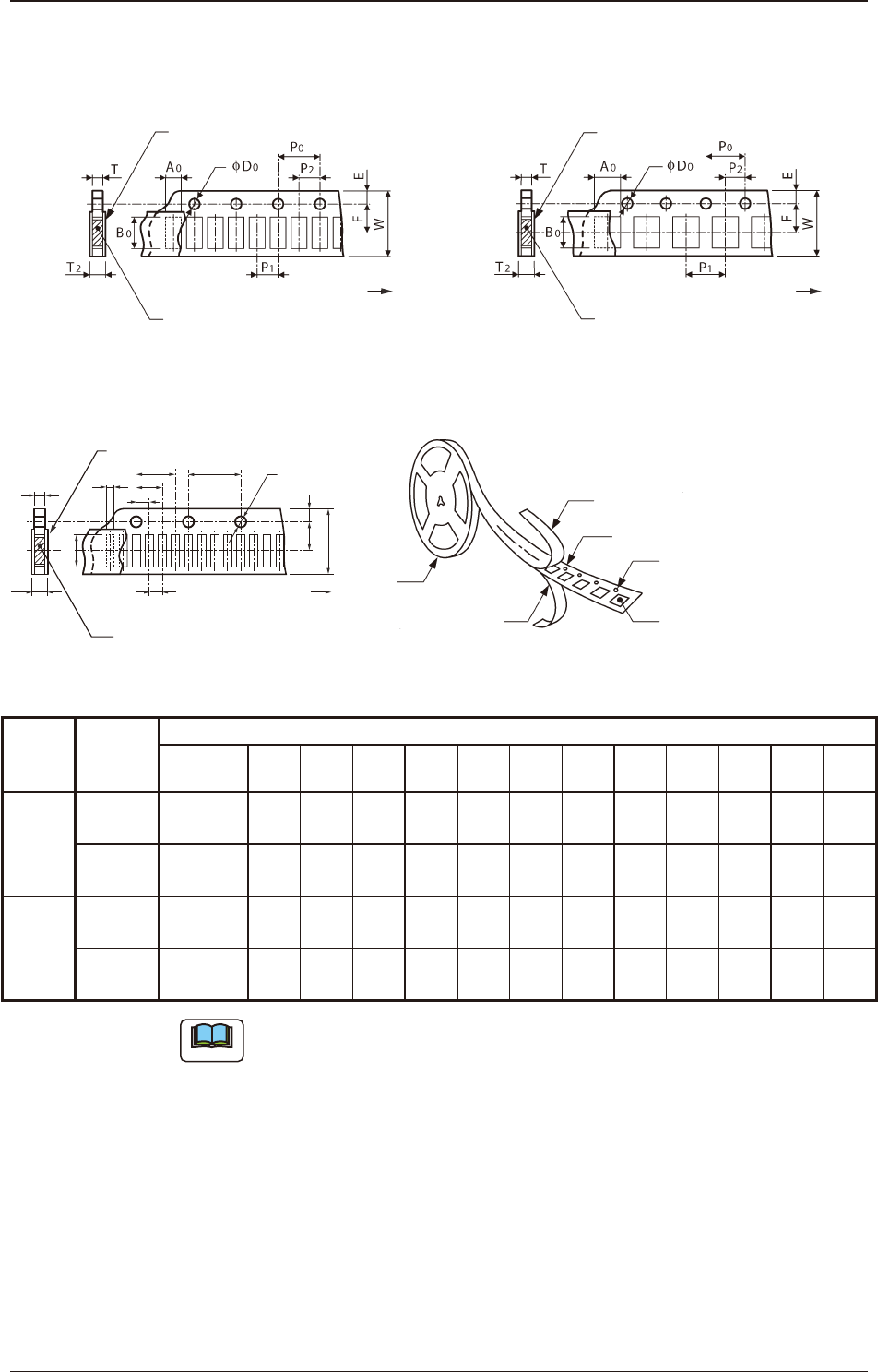
8.1.1 Referential Dimension for Taping (8 mm Paper)
Rectangle Hole Punched Carrier Type Taping Rectangle Hole Punched Carrier Type Taping
Cover Tape
Taped Component
Direction of Unreeling
(Sprocket Hole)
Cover Tape
Taped Component
(Sprocket Hole)
Direction of Unreeling
Fig. H1 Rectangle Hole Pitch (2 mm) Fig. H2 Rectangle Hole Pitch (4 mm)
Rectangle Hole Punched Carrier Type Taping
P
2
P
1
T
2
T
A
0
B
0
P
0
φ
D
0
(Sprocket
Hole)
Direction of Unreeling
Taped Component
Cover Tape
F E
W
P
3
P
4
Cover Tape
Rectangle Punched Carrier Tape
Sprocket Hole
Rectangle Hole Component
Compartment
Reel
Bottom Cover Tape
Fig. H3 Rectangle Hole Pitch (1 mm) Fig. H3-1
Table H2
Model
Tape Width
×
Feed Pitch
(mm)
Dimensions for Taping (mm)
A
0
B
0
W F E P
1
P
2
P
3
P
4
P
0
D
0
T T
2
GT-38080
GD-38080
8 × 2
More than 0.5
to 0.8 or less
1.2
or less
8.0
±
0.1
3.5
±
0.05
1.75
±
0.1
2.0
±
0.05
2.0
±
0.05
- -
4.0
±
0.1
φ
1.5
+
0.1
0
0.7
or less
0.7
or less
8 × 4
More than 0.8
to 3.4 or less
4.3
or less
8.0
±
0.1
3.5
±
0.05
1.75
±
0.1
4.0
±
0.1
2.0
±
0.05
- -
4.0
±
0.1
φ
1.5
+
0.1
0
1.1
or less
1.1
or less
GD-38083
8 × 1
More than 0.2
to 0.7 or less
1.2
or less
8.0
±
0.1
3.5
±
0.05
1.75
±
0.05
1.0
±
0.05
1.0
±
0.05
2.0
±
0.05
3.0
±
0.05
4.0
±
0.05
φ
1.5
+
0.1
0
0.6
or less
0.6
or less
8 × 2
More than 0.2
to 0.7 or less
1.2
or less
8.0
±
0.1
3.5
±
0.05
1.75
±
0.05
2.0
±
0.05
2.0
±
0.05
- -
4.0
±
0.05
φ
1.5
+
0.1
0
0.6
or less
0.6
or less
Note
(a) A
0
×
B
0
stands for the rectangle hole size on the tape.
The clearance between a rectangle hole and a component affects the pick-
up rate.
Use the taping component with appropriate clearance specications.
(b) The above specications do not imply any guarantee of pick-up rate, etc.
The pick-up rate varies depending on how the main machine is adjusted
and the combination of the main machine and the tape feeders.
(c) The clearance between the centerlines of the cavity and the sprocket hole
should be 0.05 mm or less.
(d) 10 pitches cumulative tolerance P
0
should be ± 0.2 mm.
1209-001
8.1 Specications of 8 mm Dual Tape Feeder
OM-1743
8-2