OM-1743-005w.pdf - 第60页
3.2 T ape Feeder Detachment Procedure CAUTION Do not drop the tape feeder , when attaching or detaching. Some tape feeder models are rather heavy . In the case that the feeder is removed with one hand, your hand might no…
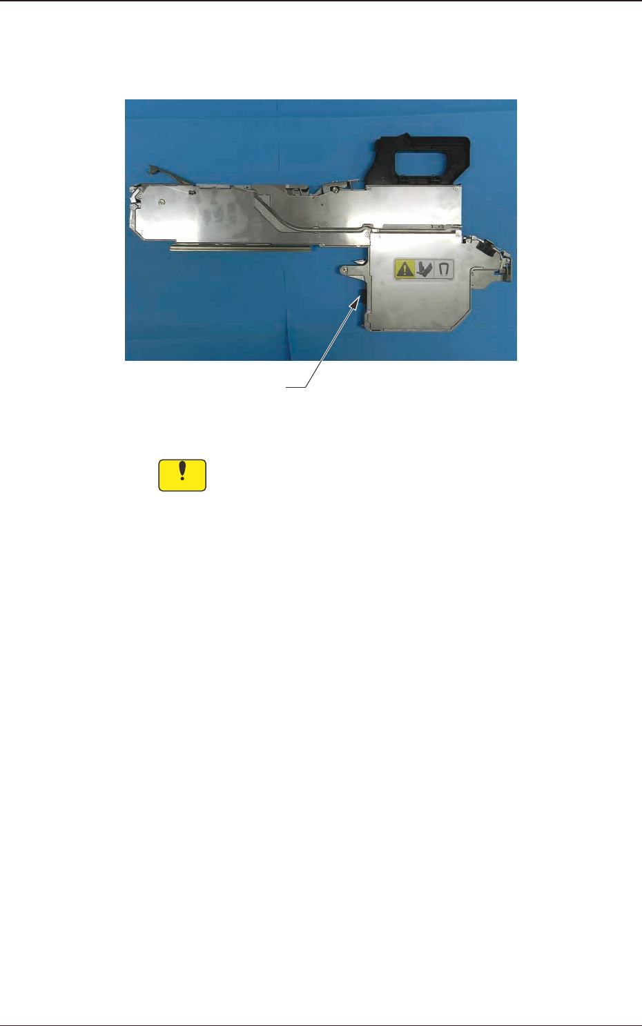
(5) Hold the grip, and insert it forward carefully until a click sound is heard.
At the same time, make sure that the tape feeder connector has been securely
connected.
Connector
Fig. C4
Notice
•
If the machine is used with the tape feeder lifted, it might cause
machine (SIGMA-G4/G5) breakdown or pick-up error.
Mount the tape feeder securely on the feeder base.
•
Remove the unused tape feeders from the bank feeder change
cart.
Also, if the machine has been operated for a long time with
such unused tape feeders attached, then the tape will have
been slackened, which might cause a pick-up error.
1209-001
3.1 Tape Feeder Attachment Procedure
OM-1743
3-5
3.2 Tape Feeder Detachment Procedure
CAUTION
Do not drop the tape feeder, when attaching or
detaching.
Some tape feeder models are rather heavy.
In the case that the feeder is removed with one hand, your
hand might not be able to support the feeder weight when
it is removed from the base, which might cause a fall of
the feeder.
Falling of a tape feeder might cause an injury on your feet
or damage to the feeder.
Hold such feeder with your both hands one by one and
take care not to drop it.
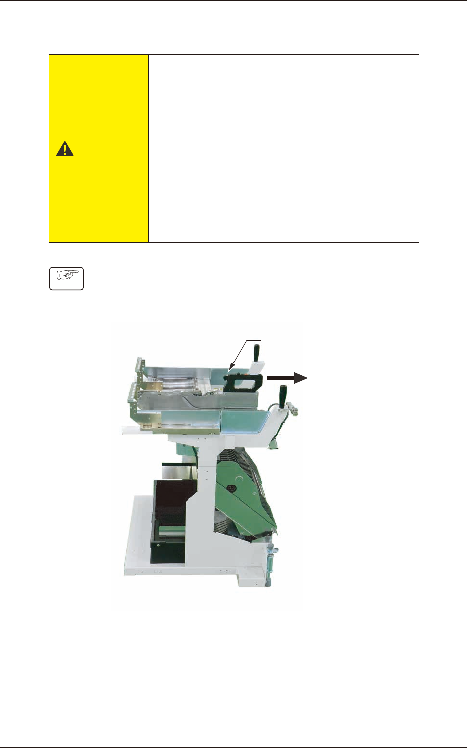
Procedure
(1) Press the clamp cancel lever.
(2) Draw the tape feeder carefully to this side.
Clamp Cancel Lever
Fig. C5
1209-001
3.2 Tape Feeder Detachment Procedure
OM-1743
3-6
4. Operation Panel
On the operation panel, the following displays and operations are available.
•
Display of the set pitch
•
I/O status display for the sensor, etc.
•
Display of the selected lane
•
Subject Lane Selection
•
Tape Feeding
•
Feed Pitch Setting
•
Display of the error codes
•
Tape returning operation
•
Display of the splicing guide
•
Cover Tape Take-up Operation
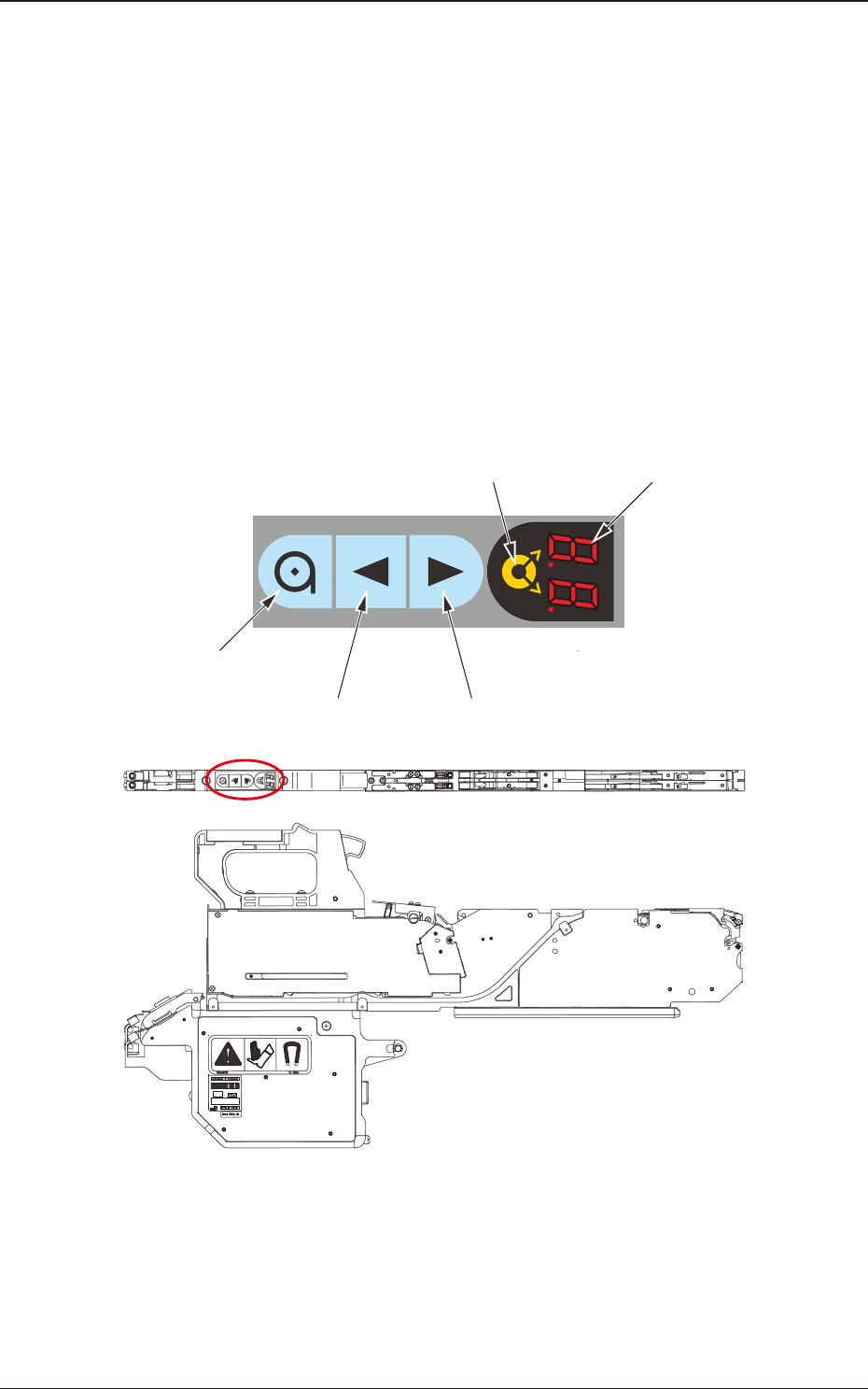
4.1 Name and Function of Each Section on Operation Panel
The tape feeder operation buttons and indicators are arranged integrally on the
operation panel.
Operation Panel
Digital IndicatorLane Selection Button
Forward ButtonBackward Button
Take-up Button
Fig. D1
1209-001
4. Operation Panel
OM-1743
4-1