OM-1743-005w.pdf - 第149页
1 1.7 Flow Chart for Identifying the Cause of Pick-up Error This ow chart is to identify the cause when any component pick-up error occurs. 1 1.7.1 A V ertical Component Occurs A vertical component occurs frequently. Re…
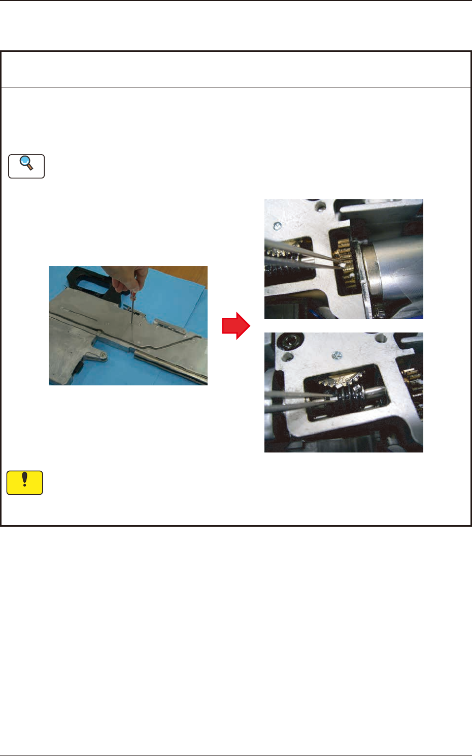
11.6 Cover Tape Take-up Gear does not rotate
1209-001
Remedy
: Remove any chip component or foreign substance such as debris entered in the gear
section and completely clean the gear.
Lubricate after clean the cover tape take-up gear section.
Refer to "Cover Tape Take-up Gear Section" in "7.3.3 Quarterly Maintenance" for details.
If the take-up gear is operated while any foreign substance has been entered, it might cause
abrasion.
Therefore, remove any of them.
Cause : Chip component or foreign substance such as debris has been entered
the take-up gear section and take-up rotation error occurs.
Notice
Reference
11.6 Cover Tape Take-up Gear does not rotate
OM-1743
11-9

11.7 Flow Chart for Identifying the Cause of Pick-up Error
This ow chart is to identify the cause when any component pick-up error occurs.
11.7.1 A Vertical Component Occurs
A vertical component
occurs frequently.
Recall Check
Does it occur on the same nozzle?
Is the line sensor measured value the same?
Pick-up height setting check
The pick-up height setting in the library is
proper?
Are the settings of simplified packing type and
feeder offset B correct?
Pick-up position check
Is the pick-up position not deviated?
Component Check
Is the clearance for the component pocket too
large?
Clean the nozzle.
Clean the line sensor.
Teach the pick-up position.
Adjust the pick-up position
(using the feeder adjusting jig).
Standard Pick-up Height Setting
8 mm Width Paper Taping
0603 Size : -0.1 mm
1005 Size : -0.05 mm
1608 Size : 0 mm
8 mm Width Embossed Taping
0 mm (regardless of the size)
Turn off the pick-up position adjusting
function.
Observable Event
Check Item
Remedial Procedure
11.7.2 Condition of No Component Occurs
Observable Event
Check Item
Condition of no
component occurs
frequently.
Splicing Check
Is the cut position for the splicing appropriate?
Suppressor Check
Is the carrier tape perforation engaged with the
sprocket teeth?
Insert the tape into the pilot pin of the
cut jig and cut the tape.
Reset the tape.
Make sure that there is nothing to
prevent the tape from running.
Remedial Procedure
1209-001
11.7 Flow Chart for Identifying the Cause of Pick-up Error
OM-1743
11-10
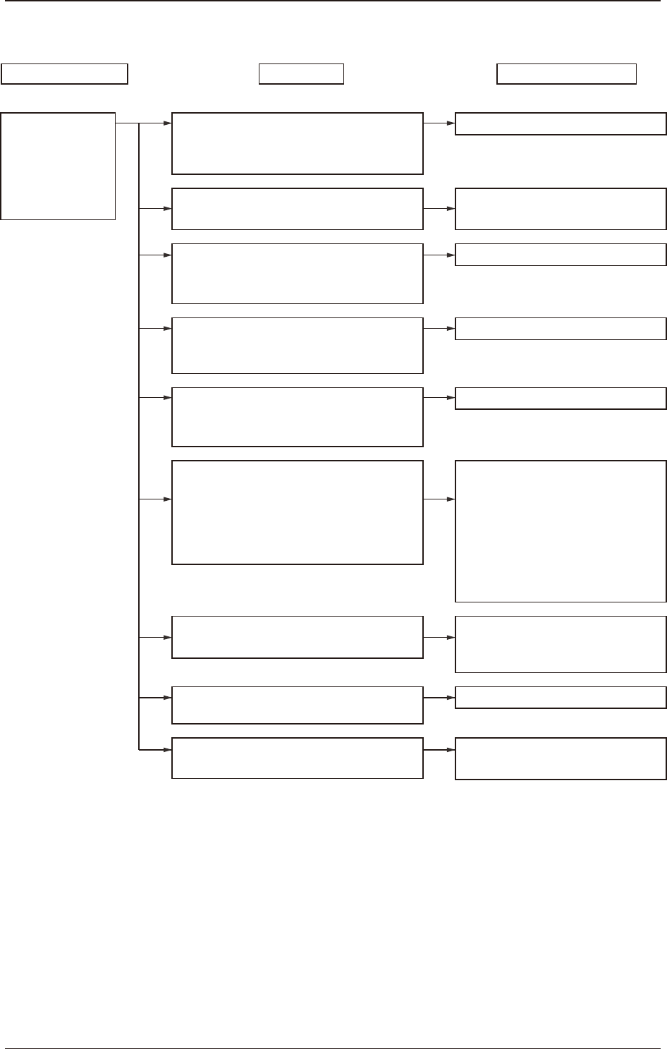
11.7.3 Both Conditions of "No component" and "Vertical component" Occur
Pick-up height setting check
The pick-up height setting in the library is
proper?
Are the settings of simplified packing type and
feeder offset B correct?
Recall Check
Does it occur on the same nozzle?
Is the nozzle clogged?
Suppressor Check
Is the component caught by the suppressor?
Suppressor Check
Is the component or splicing tape attached to
the rear of the suppressor?
Suppressor Check
Is the suppressor closed with the tape routed
incorrectly on the tape guide?
Chute Check
Is the component or splicing tape attached to
the chute?
Pick-up position check
Is the pick-up position not deviated?
Suppressor Check
Is the suppressor deformed?
Head vacuum filter Check
Is the vacuum filter clogged?
Teach the pick-up position.
Adjust the pick-up position
(using the feeder adjusting jig).
Clean the nozzle.
Clean the rear of the suppressor.
Reset the tape.
Clean the chute.
Standard Pick-up Height Setting
8 mm Width Paper Taping
0603 Size : -0.1 mm
1005 Size : -0.05 mm
1608 Size : 0 mm
8 mm Width Embossed Taping
0 mm (regardless of the size)
Replace the vacuum filter with a new
one.
Replace the suppressor with a new one.
Both conditions of
"No component"
and
"Vertical component"
occur frequently.
Remove the component and set the
tape.
Observable Event
Check Item
Remedial Procedure
1209-001
11.7 Flow Chart for Identifying the Cause of Pick-up Error
OM-1743
11-11