OM-1743-005w.pdf - 第34页
(5) Insert the tape into the tape outlet guide. (This work is to be performed only for the dual tape feeder with 8 mm width.) Cover Tape Suppressor Peeling Section Carrier Tape Tape Outlet Guide Fig. B6 (6) Pass the cove…
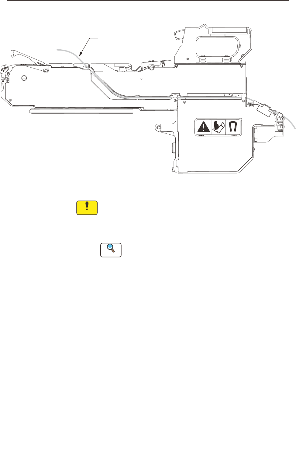
(4) Set the tape along the groove.
Tape
Fig. B5
Notice
(a) After removing the adhesive tape xing the cover tape, set the
tape.
(b) Set the tape along the groove after inserting the tape into the
guide of the joint detection unit.
Reference
Refer to "2.5 Joint Detection Unit" for details.
1305-003
2.1 Attachment of Paper or Embossed Tape
OM-1743
2-3
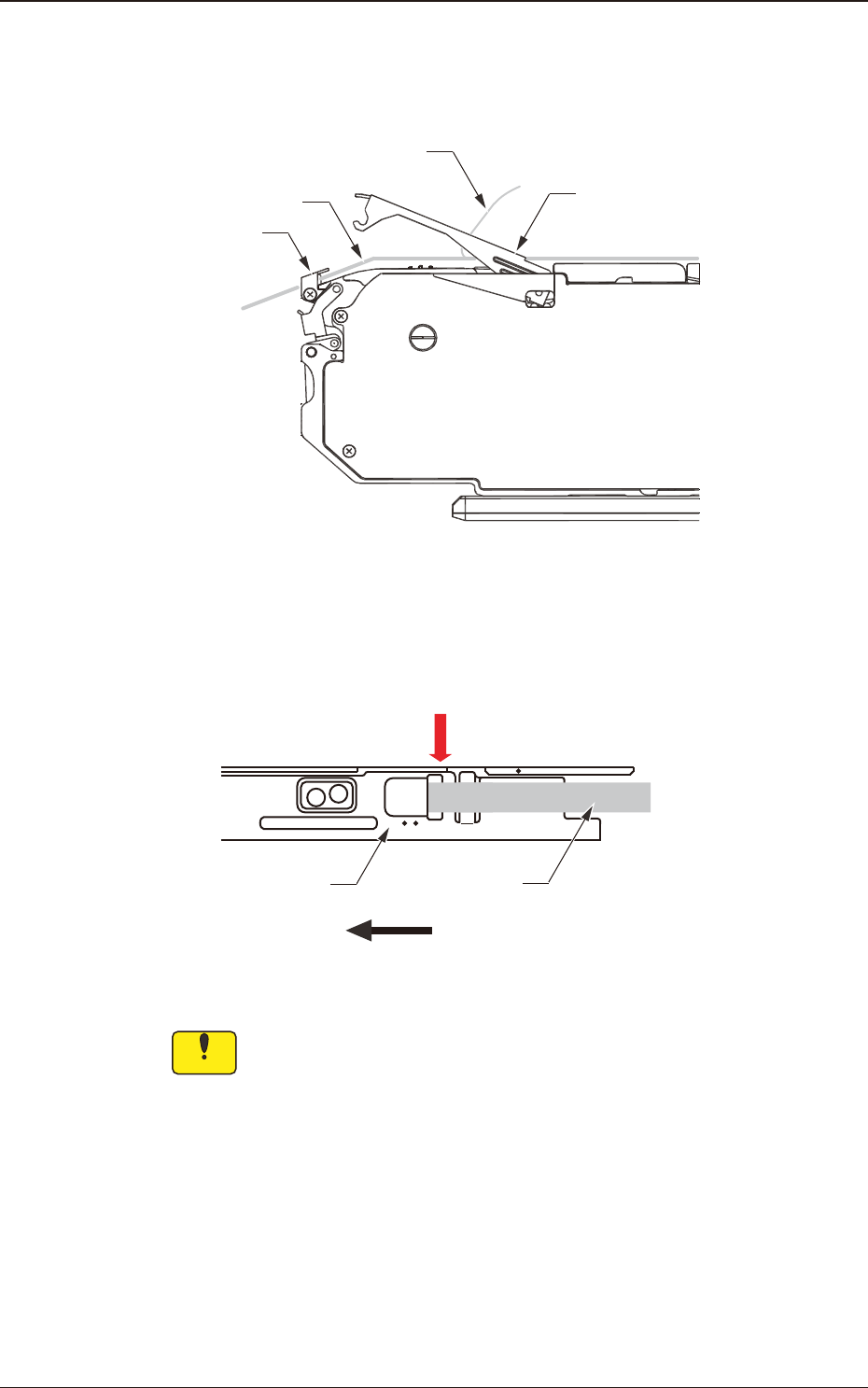
(5) Insert the tape into the tape outlet guide.
(This work is to be performed only for the dual tape feeder with 8 mm
width.)
Cover Tape
Suppressor Peeling
Section
Carrier Tape
Tape Outlet Guide
Fig. B6
(6) Pass the cover tape through the slit in the peeling section.
4
2
Cover Tape
Direction of Feed
Suppressor
Through
Fig. B7
Notice
Do not forcibly pull the cover tape.
1305-003
2.1 Attachment of Paper or Embossed Tape
OM-1743
2-4
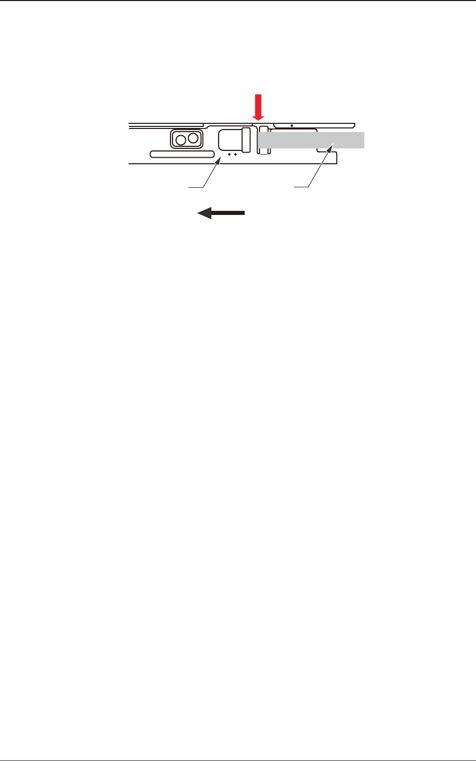
•
In the case that the component posture becomes unstable due to static electricity
generated when the cover tape is peeled off, pass the cover tape through the slit
of the peeling off section.
4
2
Suppressor Cover Tape
Direction of Feed
Through
Fig. B8
1305-003
2.1 Attachment of Paper or Embossed Tape
OM-1743
2-5