OM-1743-005w.pdf - 第36页
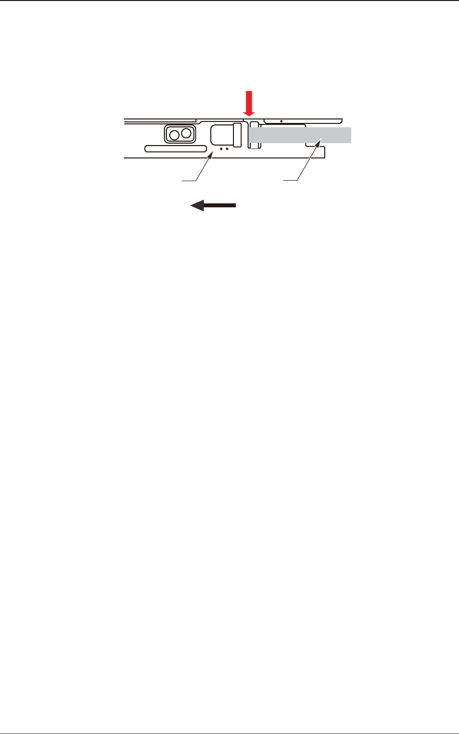
(7) Set the carrier tape in the chute section so that the sprocket pins are securely engaged with the sprocket holes. (8) Make sure that components are not scattered on the carrier tape. (9) Lower the suppressor carefull…
•
In the case that the component posture becomes unstable due to static electricity
generated when the cover tape is peeled off, pass the cover tape through the slit
of the peeling off section.
4
2
Suppressor Cover Tape
Direction of Feed
Through
Fig. B8
1305-003
2.1 Attachment of Paper or Embossed Tape
OM-1743
2-5
(7) Set the carrier tape in the chute section so that the sprocket pins are securely
engaged with the sprocket holes.
(8) Make sure that components are not scattered on the carrier tape.
(9) Lower the suppressor carefully.
Push down the suppressor so that it does not mount on the chute.
(10) Make sure that the cover tape or chip component is not caught in the peeling
section.
Notice
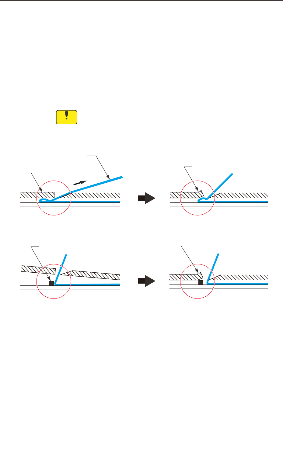
If the cover tape or the chip component gets caught by the suppressor,
then the peeling section might be deformed or a pick-up error occur.
If there is any such catching of the cover tape or chip component, do not
pull it out forcibly; just lift the suppressor.
If operation is performed with the
cover tape caught in the
suppressor . . .
The peeling section might be
deformed.
If the suppressor is lowered with
any foreign substance on the tape
surface . . .
The peeling section might be
deformed.
Deformation
Cover Tape
Suppressor
Foreign Substance
Deformation
Fig. B9
1209-001
2.1 Attachment of Paper or Embossed Tape
OM-1743
2-6
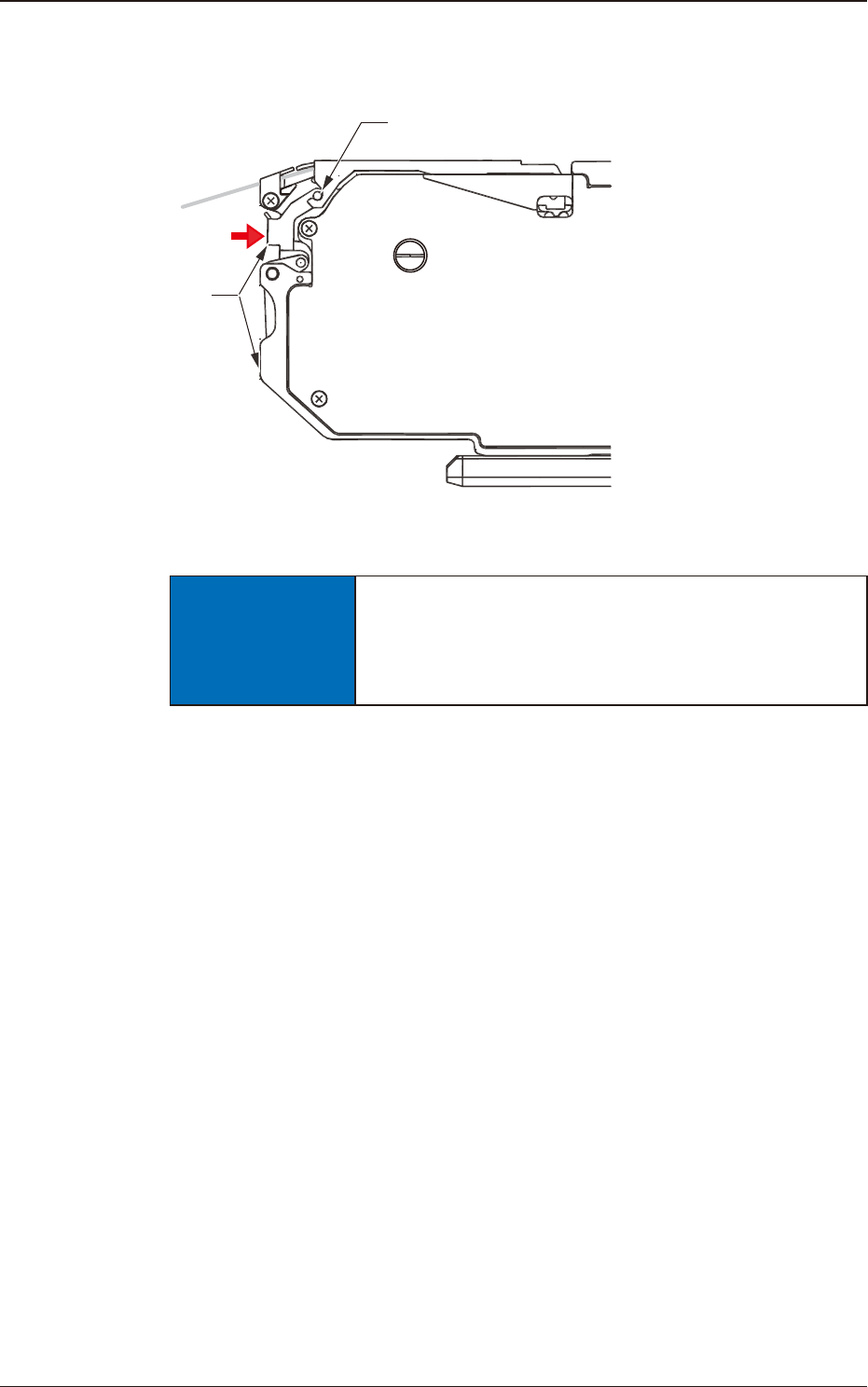
(11) Maintain the suppressor being lowered: press the upper section of the front
hook to x the suppressor.
Fix the suppressor with the front hook.
Front Hook
Press
Fig. B10
NOTICE
Securely lock the suppressor with the front hook.
If the tape feeder is operated while the suppressor is
raised, the machine (SIGMA-F8) might be damaged
or incur a pick-up error.
1209-001
2.1 Attachment of Paper or Embossed Tape
OM-1743
2-7