OM-1743-005w.pdf - 第91页
Bend the splicing tape along the perforations and adhere it onto the carrier tape on the sprocket hole border side. In order to adhere the splicing tape securely , press and rub the surface of the transparent tape entire…
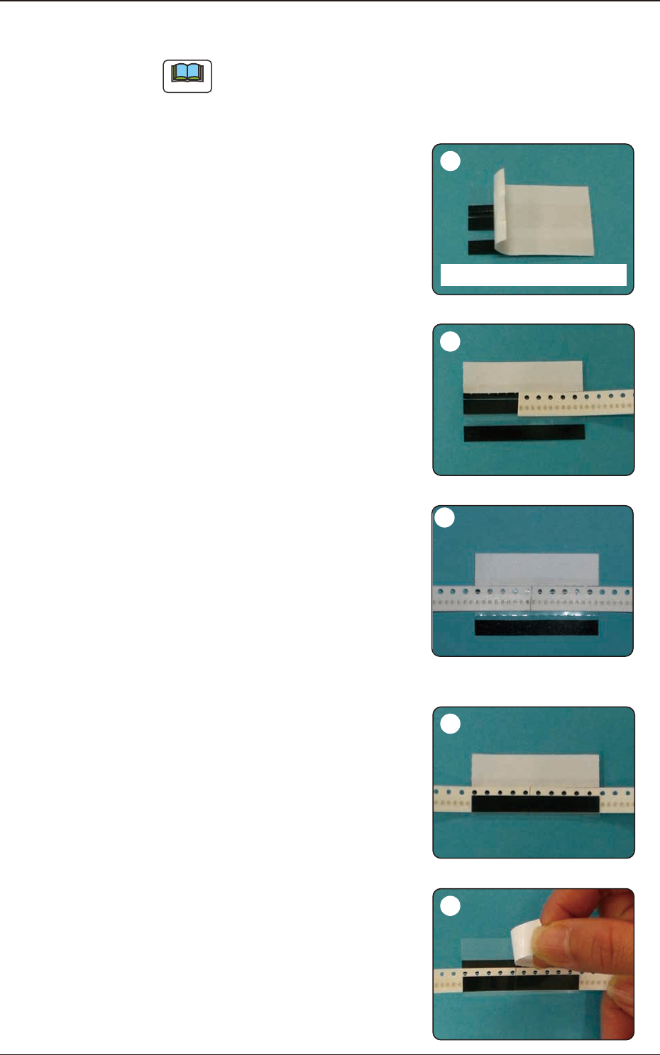
6.5.3 Tape Splicing Procedure (For 8 mm : HT8RE)
Note
When part of black tape is left on the peeling paper, return the peeling
paper and press the tape against the paper. Then, peel off the peeling paper
again.
Peel off the white peeling paper
located on the section with oblique
lines in the above gure.
As there is a margin for peeling, peel
it from that section.
First, adhere the cover tape surface
of the new tape onto the splicing
tape.
Align the tape border of the sprocket
hole side with the left white peeling
paper, and so adhere it that the joint
position is located at the center.
Adhere the cover tape surface on the
feeder side.
Align the tape border of the sprocket
hole side with the left white peeling
paper, and so adhere it that there is
no gap on the joint position with the
new tape.
Bend the splicing tape along the
perforations and adhere it onto the
carrier tape.
Peel off the white peeling paper from
the sprocket hole border side.
1209-001
2
5
4
1
Other Side of Splicing Tape
3
6.5 8 mm Width Tape Splicing Procedure
OM-1743
6-10
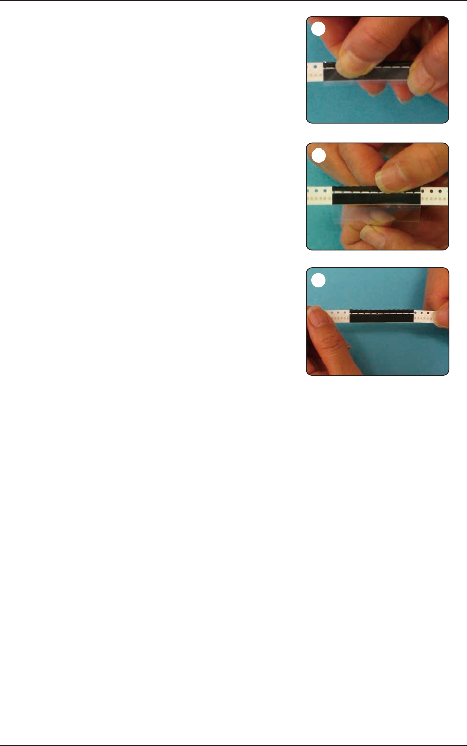
Bend the splicing tape along the
perforations and adhere it onto the
carrier tape on the sprocket hole
border side.
In order to adhere the splicing tape
securely, press and rub the surface
of the transparent tape entirely.
Peel off the transparent lm.
Conrm that the splicing tape has
been adhered securely to the cover
tape and the carrier tape surfaces.
When the tape has been spliced
securely, the procedure is completed.
1209-001
6
7
8
6.5 8 mm Width Tape Splicing Procedure
OM-1743
6-11
1209-001
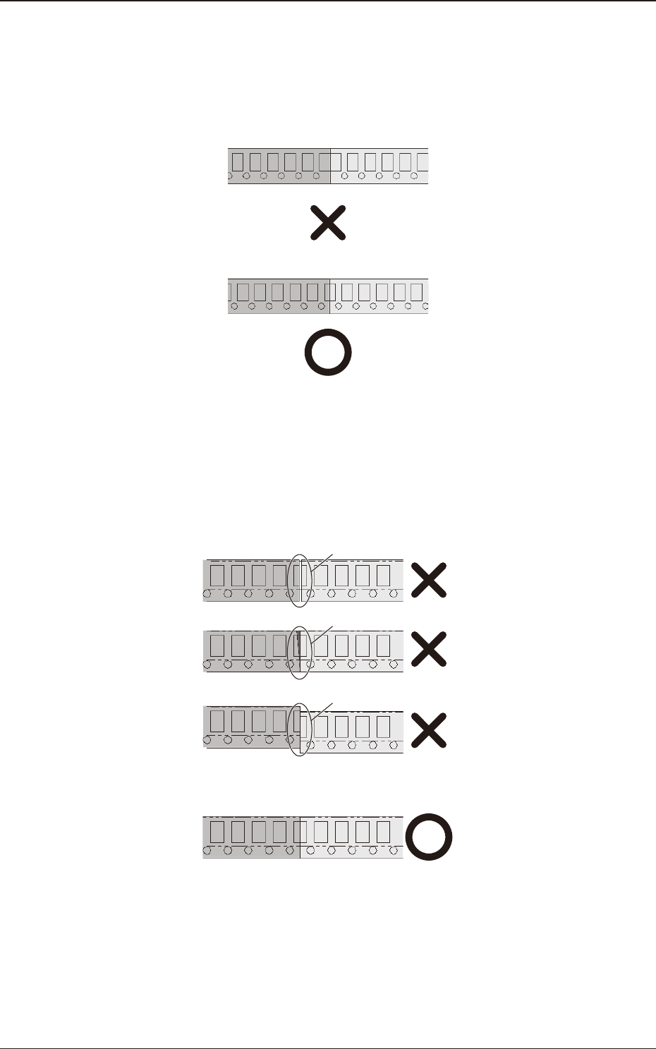
6.5.4 Precautions
(1) When the carrier tape is cut or spliced, take care so that the
component feed pitch does not slide.
Otherwise, the pick-up error might occur.
(2) Cut and splice the carrier tape so that there is no gap, overlap or
deviation of the carrier tape on the joint position.
Cut the tape at an angle of 90 degrees to the long side and at the
same position, based on the sprocket hole.
If there is any gap, overlap or deviation, a feed error might occur.
Gap
Overlap
Deviation
6.5 8 mm Width Tape Splicing Procedure
OM-1743
6-12