OM-1743-005w.pdf - 第53页
1209-001 • Adjusting Procedure Procedure (1) Loosen the hexagon nut. (2) Turn the groove on the adjusting bolt three times cloc kwise using a screwdriver . (When the bolt is turned around three times from the standard po…
1209-001
2.7 8 mm Cover Tape Tension Lever Section Spring Setup
•
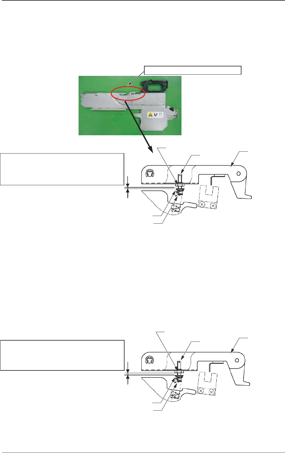
Cover Tape Tension Lever Section Spring Standard Set Value
For the spring standard set values, the gap distance between the adjusting bolt
ange section and the hexagon nut should be "0.7 mm".
Adjusting Screw of Flange
Tension Lever Section Spring Set Position
Standard Set Position:
Gap distance of "0.7 mm" between the flange
and hexagon nut
Cover Tape Tension Lever Section
Adjusting
Bolt
Spring
Tension Lever
Hexagon Nut
Fig. B27
•
Setting when a cover tape take-up error (E1 Error) occurs frequently
during the tape feeder operation
Depending on the cover tape type, the tape might not be taken up normally and
might be caught in the suppressor releasing section gap, in the case that the
spring has been set to "standard".
When this error occurs frequently, change the tension lever spring setting as
shown in the following gure.
Tension Lever Section Spring Set Position
Changed Position:
Gap distance of "1.7 mm" between the flange
and hexagon nut
Adjusting
Bolt
Tension Lever
Hexagon Nut
Spring
Adjusting Screw of Flange
Fig. B28
2.7 8 mm Cover Tape Tension Lever Section Spring Setup
OM-1743
2-22

1209-001
•
Adjusting Procedure
Procedure
(1) Loosen the hexagon nut.
(2) Turn the groove on the adjusting bolt three times clockwise using a
screwdriver.
(When the bolt is turned around three times from the standard position, the
gap distance between the ange and hexagon nut becomes "1.7 mm" and the
tape take-up strength becomes 1.2 times more of the standard strength.
(3) Return the hexagon nut to the upper surface position and x.
2.7 8 mm Cover Tape Tension Lever Section Spring Setup
OM-1743
2-23

1209-001
OM-1743
2-24