OM-1743-005w.pdf - 第123页
(2) Check the sensor detection status. Shield the sensor from the light and check that the sensor detection is normal. Pass a thin paper through the sensor section in the joint detection unit to shield the sensor from th…
7.5.4.3 Sensor Detection Check
Procedure
(1) Check the sensor detection.
The sensor I/O status can be checked in the digital display section on the
operation panel.
Turn ON the power to the tape feeder and perform the following operations
to check the sensor status.
•
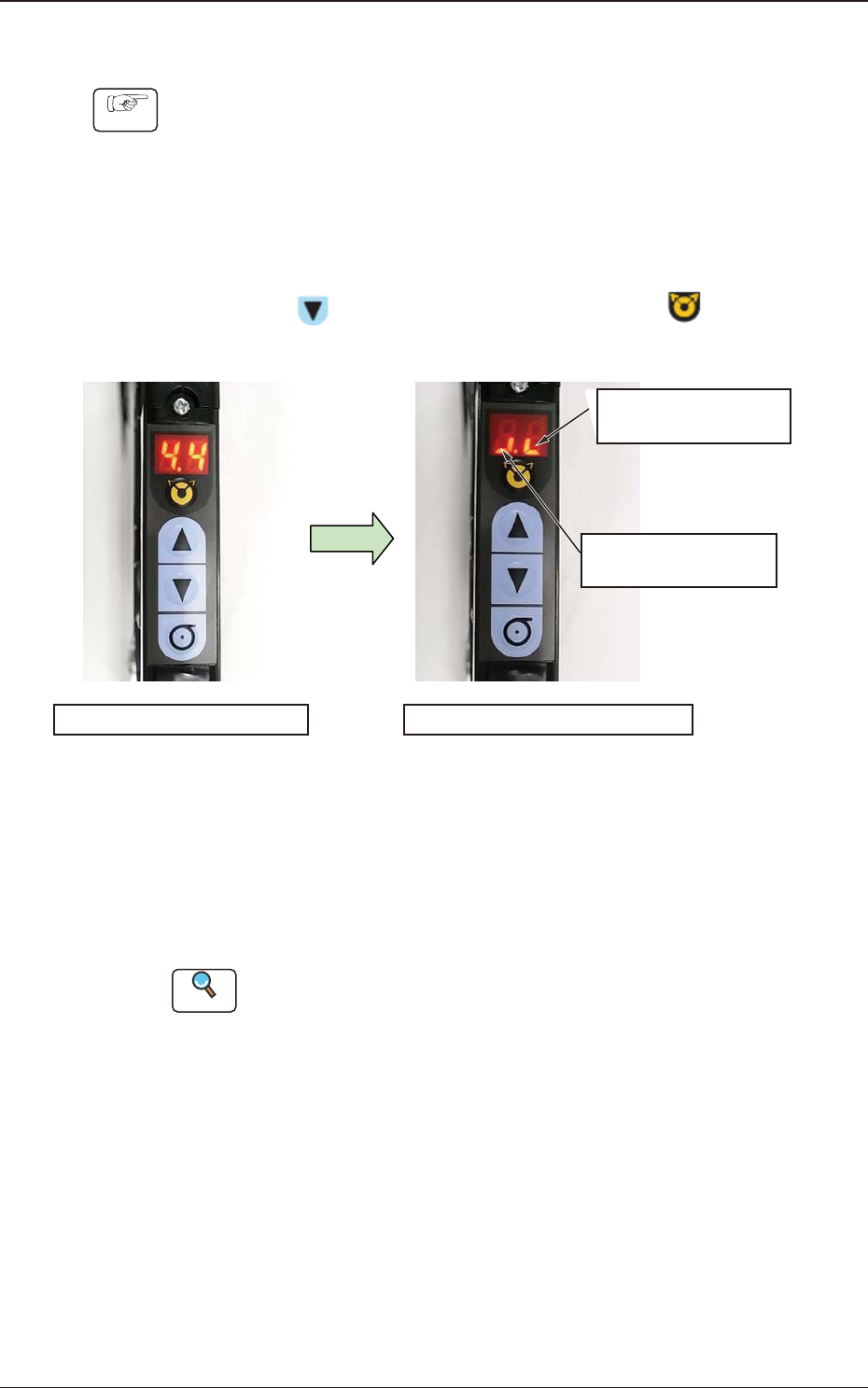
Sensor I/O Status Display Mode Change
Press the
button and within 2 seconds, press the button. Keep
this condition (two buttons are being pressed) for 2 seconds.
Normal Mode Panel Display
Sensor I/O Status Display Mode
It shows the Lane 1
Sensor Status.
It shows the Lane 2
Sensor Status.
Mode Change
Fig. G41
When the mode is changed to the Sensor I/O Status Display Mode, the
lighting display (ON Status) appears as shown in the upper right picture.
In the case that any dirt or debris is stuck to the sensor, or the sensor is
broken down, the display might be turned OFF (OFF Status).
Reference
Refer to "4.2.10 I/O Status Indication for Sensor, etc." for details.
1209-001
7.5 Maintenance Method
OM-1743
7-28
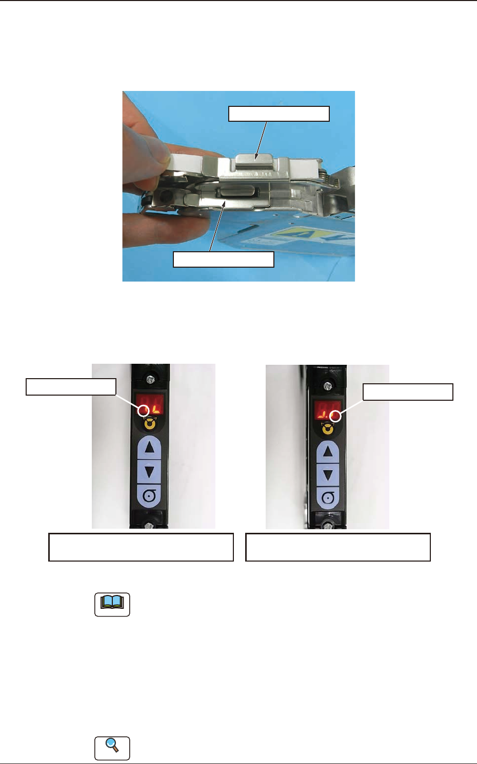
(2) Check the sensor detection status.
Shield the sensor from the light and check that the sensor detection is normal.
Pass a thin paper through the sensor section in the joint detection unit to
shield the sensor from the light.
On the Lane 1 Side
On the Lane 2 Side
Fig. G42
When the sensor is normal, the status in the display section becomes ON to
OFF status. When this is conrmed, it is regarded that the joint detection
sensor functions normally.
Panel Display in Shielding the Sensor
on the Lane 2 Side from the Light
ON to OFF Status
ON to OFF Status
Panel Display in Shielding the Sensor
on the Lane 1 Side from the Light
Fig. G43
Note
Make sure to check both sensors on the Lane 1 and Lane 2 sides.
(3) End the sensor I/O status display mode.
There are two mode ending procedures as follows.
Procedure 1
: Turn off the power to the tape feeder. When the power is
turned ON again, the mode is returned to the normal mode.
Procedure 2
: Perform the same procedure as the mode changing operation
to sensor I/O status mode.
Reference
Refer to "4.2.10 I/O Status Indication for Sensor, etc." for details.
1209-001
7.5 Maintenance Method
OM-1743
7-29
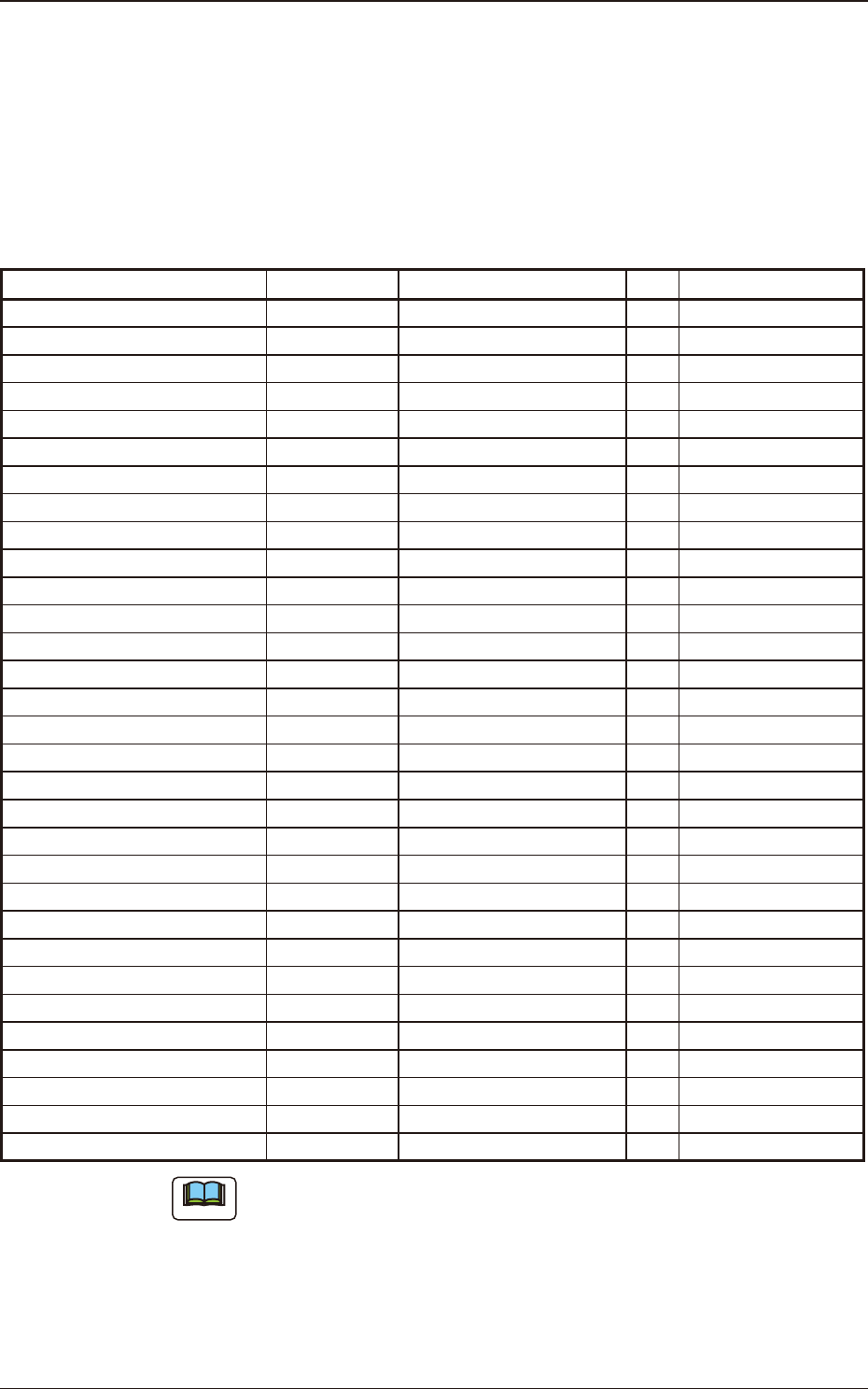
7.6 Maintenance Component List
Listed below are the parts for which maintenance work is required in several
years. The list below is provided for your reference.
If the recommended years of the component has passed or the component is
damaged, replace it.
GT-38080 and GD-38080 Maintenance Component List
Table G5A
Component Name PART No. PART NAME Q'ty
Recommended
Years
Worm Wheel ASSY (L) KYD-MC112-00 ASSY_GEAR(L) 1 3 years / 30 million feeds
Worm Wheel ASSY (R) KYD-MC113-00 ASSY_GEAR(R) 1 3 years / 30 million feeds
Take-up Worm Wheel KYD-MC131-00 GERA(HASUBA) 2 3 years / 20 million feeds
Take-up Worm Motor KYD-MC11S-00 MOTOR_DC 2 3 years / 16 million feeds
Timing Belt KYD-MC13V-00 BELT_TIMING 2 4 years / 40 million feeds
Take-up Gear (Flat End Wheel 1) KYD-MC130-00 GEAR(HIRA-1) 2 4 years / 20 million feeds
Take-up Gear (Flat End Wheel 2) KYD-MC12L-00 ASSY_GEAR 2 4 years / 20 million feeds
Sprocket ASSY (L) KYD-MC12G-00 ASSY_SPROCKET_L 1 -
Sprocket ASSY (R) KYD-MC12H-00 ASSY_SPROCKET_R 1 -
Cover (LA) KYD-MC10H-00 COVER(LA) 1 -
Cover (LB) KYD-MC10K-00 COVER (LB) 1 -
Cover (RB) KYD-MC10L-00 COVER (RB) 1 -
Cover (KIBAN) KYD-MC10J-00 COVER (KIBAN) 1 -
Front End Guide KYD-MC13H-00 GUIDE 1 -
Front Hook KYD-MC10T-00 ASSY_HOOK 2 -
Front Hook Spring KYD-MC12P-00 SPRING_COMP(F) 2 -
Suppressor ASSY (GT-38080) KYD-MC12M-00 ASSY_LEVER (GT-38080) 2 -
Suppressor Lock Spring KYD-MC12A-00 SPRING_COMP(SUP) 2 -
Magnetic Plate KYD-MC115-00
ASSY_PLATE (MAG)
2 -
Tension Lever ASSY (L) KYD-MC12J-00
ASSY_TENSION(L)
1 -
Tension Lever ASSY (R) KYD-MC12K-00
ASSY_TENSION(R)
1 -
Roll-in Preventive Plate KYD-MC11X-00
COVER
2 -
Scraper (L) KYD-MC13F-00
BLOCK(L)
1 -
Scraper (R) KYD-MC13G-00
BLOCK(R)
1 -
Take-up Cancel Lever (L) KYD-MC118-00
ASSY_LEVER(L)
1 -
Take-up Cancel Lever (R) KYD-MC119-00
ASSY_LEVER(R)
1 -
Conductive Grip Lever KYD-MC125-00 ASSY_GRIP 1 -
Conductive Grip Cover KYD-MC11W-00 COVER(GRIP) 1 -
Operation Panel KYD-MC121-00 PCB_MOUNT 1 -
Cover Tape Outlet Cover KYD-MC12N-00 COVER(FUTA) 1 -
Cutter KYD-MC13X-00 CUTTER 1 -
Note
(a) The numbers entitled "Recommended Years" indicate the referential values
with 4 mm feed pitch.
Replacement may be required depending on the *actual use or maintenance
status regardless of the recommended years or specied feed amount.
*When picking up components continuously with one feeder
(b) Because the cutter blade is very sharp, when the cutter is to be changed, do
not hold the blade section. Take the greatest care not to get injured.
1901-005
7.6 Maintenance Component List
OM-1743
7-30