OM-1743-005w.pdf - 第136页
1209-001 A(M804WW ---3001) 10. Electrical Circuit Diagrams 10.1 Feeder Control Circuit Diagram (GT -38080) Drawer Connector Connection Confirmation Signal Lane 1 Feed Command Lane 2 Feed Command READY Signal Connection C…
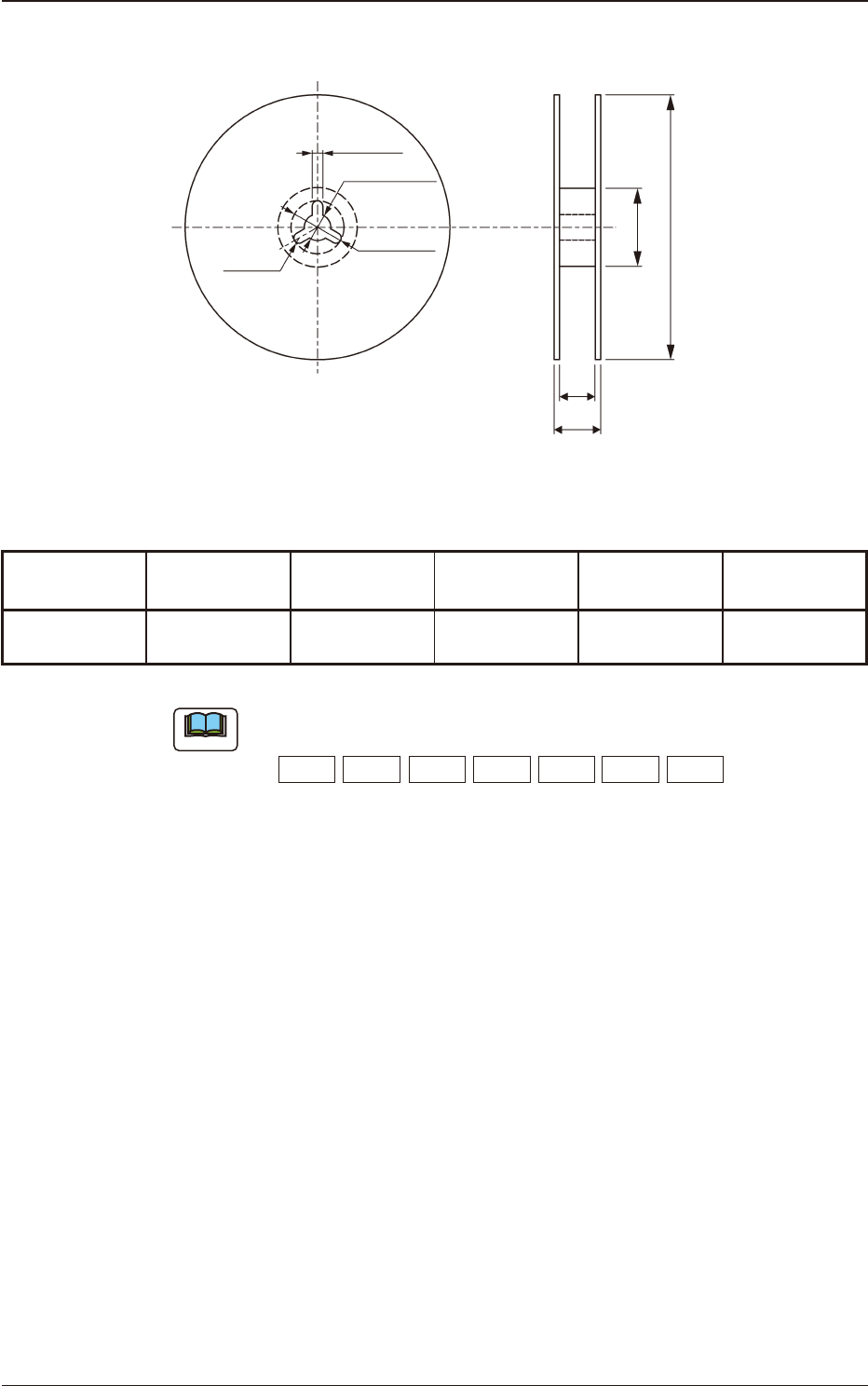
9.9 Style and Dimensions of Reel
2.0 ± 0.5
13.0 ± 0.2
21 ± 0.8
R 1.0
N A
W1
W2
Unit : mm
Fig. I8
Table I2
Classication
Symbol of Reel
Applicable
Tape Width
A N W
1
W
2
R 08 □
8
178 to 382 60 or more 8.4
+2
0
14.4 or less
Unit : mm
Note
(a) An English capital letter given below which corresponds to nominal value
of dimension A is entered into □ in classication symbol of reel.
A:178 B:180 C:254 D:330 E:360 F:370 G:382
(b) Dimension W
2
means overall thickness of the reel.
1209-001
9.9 Style and Dimensions of Reel
OM-1743
9-4
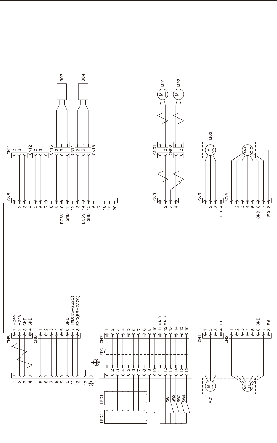
1209-001 A(M804WW---3001)
10. Electrical Circuit Diagrams
10.1 Feeder Control Circuit Diagram
(GT-38080)
Drawer Connector
Connection Confirmation Signal
Lane 1 Feed Command
Lane 2 Feed Command
READY Signal
Connection Confirmation Signal
Lane 2 Tension Detection Sensor
Lane 1 Tension Detection Sensor
White
Brown
Blue
White
Brown
Blue
Blue
Black
Blue
Black
Blue
Black
Blue
Black
Blue
Black
Blue
Blue
Black
Blue
Blue
Black
Blue
Blue
Black
Blue
Operation Panel
Cover Tape Take-up Key
7-Segment LED is turned ON (a)
7-Segment LED is turned ON (b)
7-Segment LED is turned ON (c)
7-Segment LED is turned ON (d)
7-Segment LED is turned ON (e)
7-Segment LED is turned ON (f)
7-Segment LED is turned ON (g)
7-Segment LED is turned ON (D.P)
For Dynamic Light ON (first figure)
For Dynamic Light ON (second figure)
Lane Selection Key
Forward Key
Backward Key
DC Motor No. 2 Power Supply
DC Motor No. 1
DC Motor No. 1 Power Supply
DC Motor No. 2
Lane 1 Take-up Motor
Lane 2 Take-up Motor
Lane 1 Servo Motor
Motor No. 1 Phase W
Motor No. 1 Phase U
Motor No. 1 Phase V
Reserve
Encoder No. 1 Phase A
/Encoder No. 1 Phase A
Encoder No. 1 Phase B
Power Supply (DC5V)
/Encoder No. 1 Phase B
Motor No. 2 Phase W
Motor No. 2 Phase U
Motor No. 2 Phase V
Lane 2 Servo Motor
Reserve
Encoder No. 2 Phase A
/Encoder No. 2 Phase A
Encoder No. 2 Phase B
/Encoder No. 2 Phase B
Power Supply (DC5V)
Feeder Control Amplifier
10. Electrical Circuit Diagrams
OM-1743
10-1
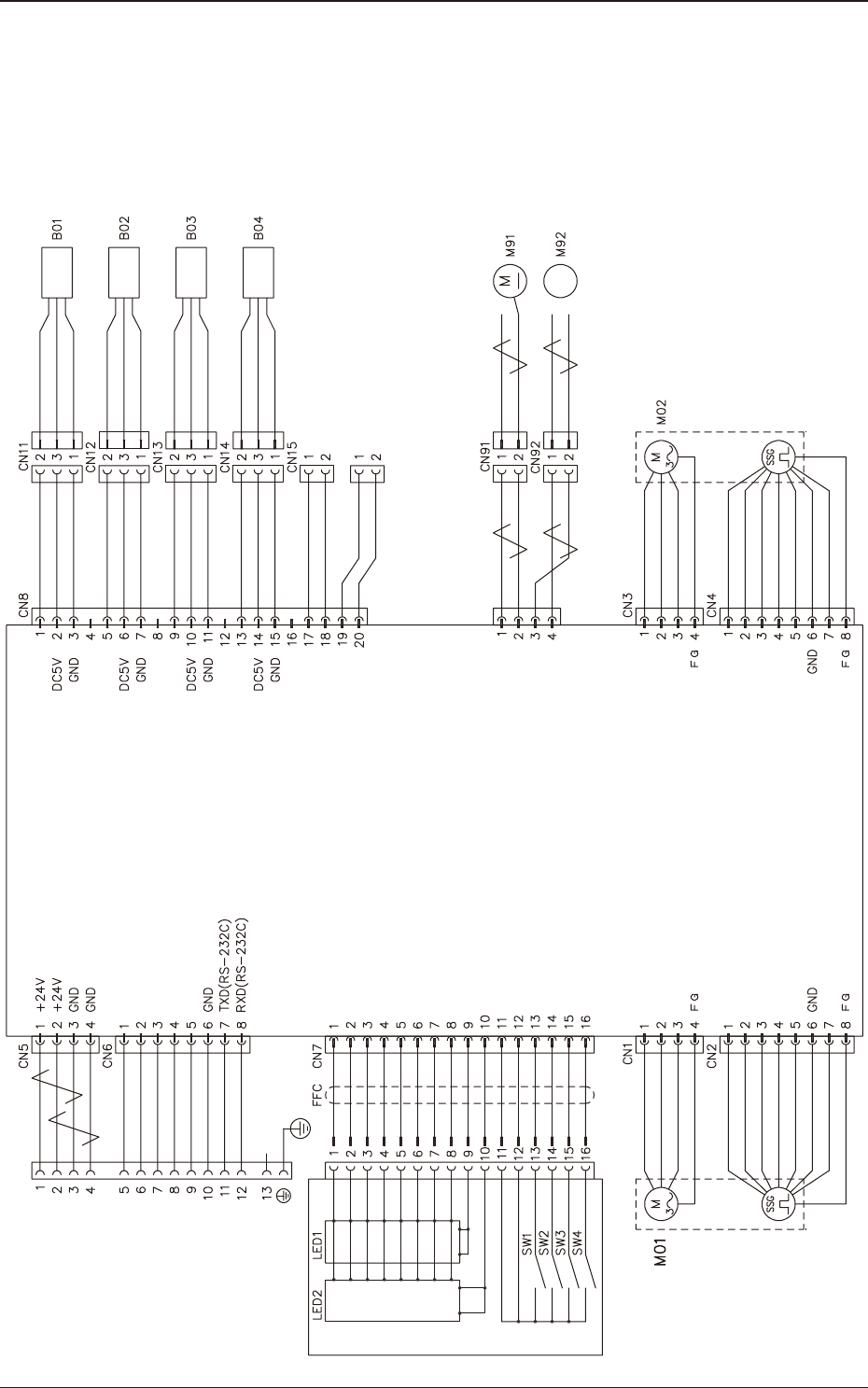
1209-001 -(M804WW---4001)
10.2 Feeder Control Circuit Diagram (GD-38080)
Drawer Connector
Lane 1 Feed Command
Lane 2 Feed Command
READY Signal
Connection Confirmation Signal
Connection Confirmation Signal
7-Segment LED is turned ON (a)
7-Segment LED is turned ON (b)
7-Segment LED is turned ON (c)
7-Segment LED is turned ON (d)
7-Segment LED is turned ON (e)
7-Segment LED is turned ON (f)
7-Segment LED is turned ON (g)
7-Segment LED is turned ON (D.P)
For Dynamic Light ON (first figure)
For Dynamic Light ON (second figure)
Cover Tape Take-up Key
Lane Selection Key
Forward Key
Backward Key
GND
GND
Motor Phase 1W
Motor Phase 1U
Motor Phase 1V
Encoder Phase 1A
/Encoder Phase 1A
Encoder Phase 1B
Power Supply (DC5V)
/Encoder Phase 1B
Feeder Control Amplifier
Lane 1 Servo Motor
Operation Panel
Lane 1 Splicing Detection Sensor
Lane 2 Splicing Detection Sensor
Lane 1 Tension Detection Sensor
Lane 2 Tension Detection Sensor
DC Motor 1
DC Motor 1 Power Supply
DC Motor 2
DC Motor 2 Power Supply
Motor Phase 2W
Motor Phase 2U
Motor Phase 2V
Encoder Phase 2A
/Encoder Phase 2A
Encoder Phase 2B
Power Supply (DC5V)
/Encoder Phase 2B
Reserve
Lane 2 Servo Motor
White
Brown
Blue
White
Brown
Blue
White
Brown
Blue
White
Brown
Blue
Blue
Black
Blue
Blue
Black
Blue
Blue
Black
Blue
Blue
Black
Blue
Blue
Black
Blue
Black
Lane 1 Take-up Motor
Lane 2 Take-up Motor
Blue
Black
Blue
Black
Blue
Black
Blue
Black
10.2 Feeder Control Circuit Diagram (GD-38080)
OM-1743
10-2