OM-1743-005w.pdf - 第47页
2.5 Joint Detection Unit Set the tape after inserting the tape into the guide of the joint detection unit. Procedure (1) Bend the cover tape at the end of the tape and pass the tape according to the tape guide from under…
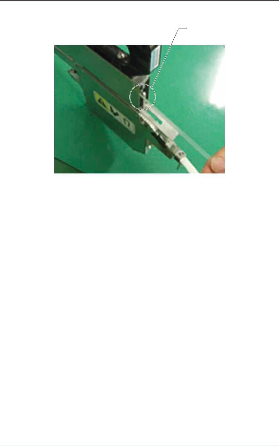
(2) Cut the drawn cover tape with the cutter in the tape feeder.
Cutter
Fig. B21
1209-001
2.4 Remove the Cover Tape
OM-1743
2-16
2.5 Joint Detection Unit
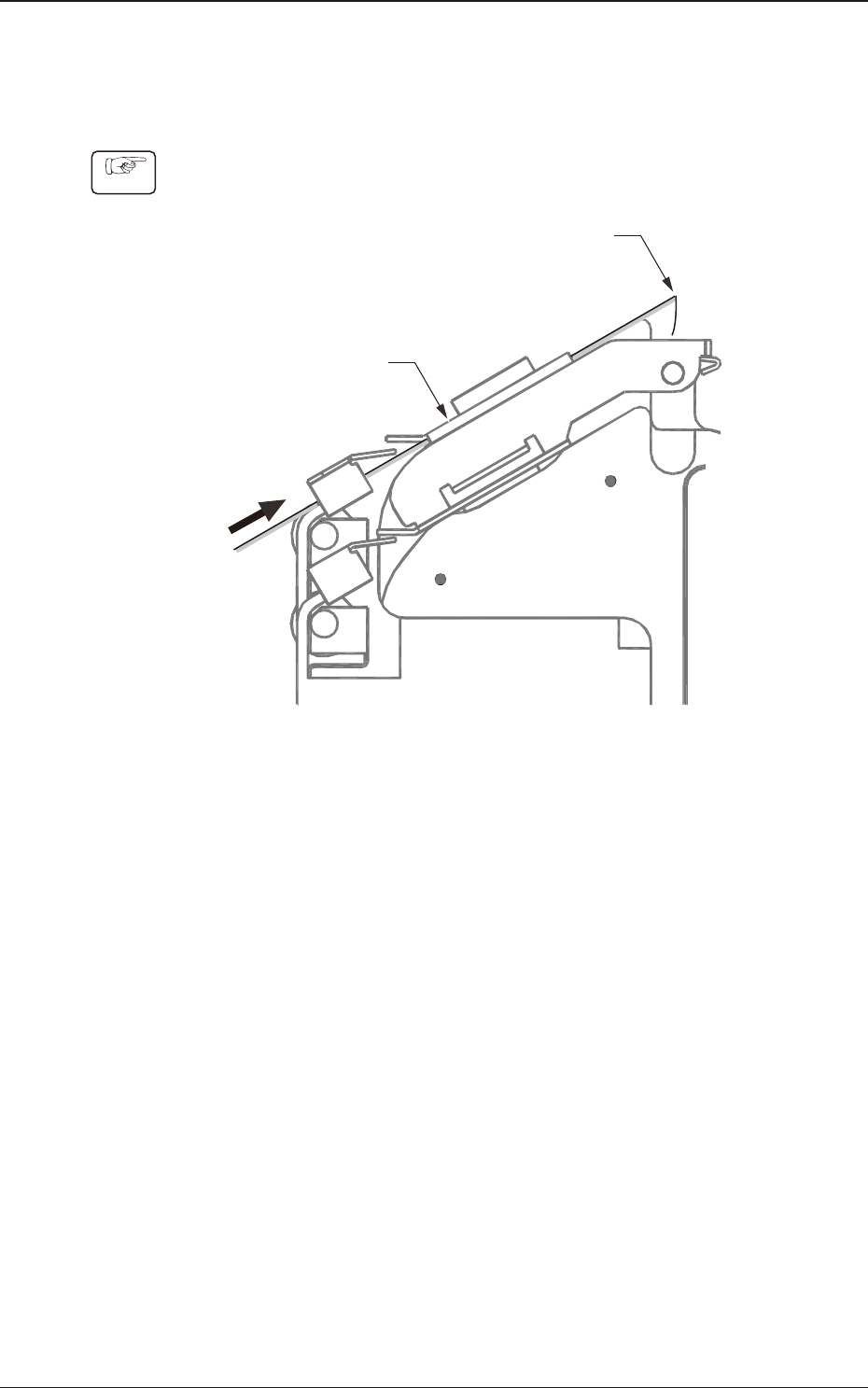
Set the tape after inserting the tape into the guide of the joint detection unit.
Procedure
(1) Bend the cover tape at the end of the tape and pass the tape according to the
tape guide from under the joint detection unit.
Pass the tape from
the lower side
Tape guide
Bend the cover tape at the end tape
Fig. B22
1209-001
2.5 Joint Detection Unit
OM-1743
2-17
2.6 Handling of Magnet Plate
In the 8 mm width dual feeder, the Magnetic Plate is attached to the chute section
to stabilize the component pick-up condition.
The effect of the magnetism varies, depending on the component type, size, and
material.
Also, for some components, the magnetism might have harmful effects on the
component characteristics or pick-up conditions.
Note
Check the effect of the magnetism on the components and if it has any adverse
effect, remove the Magnetic Plate.
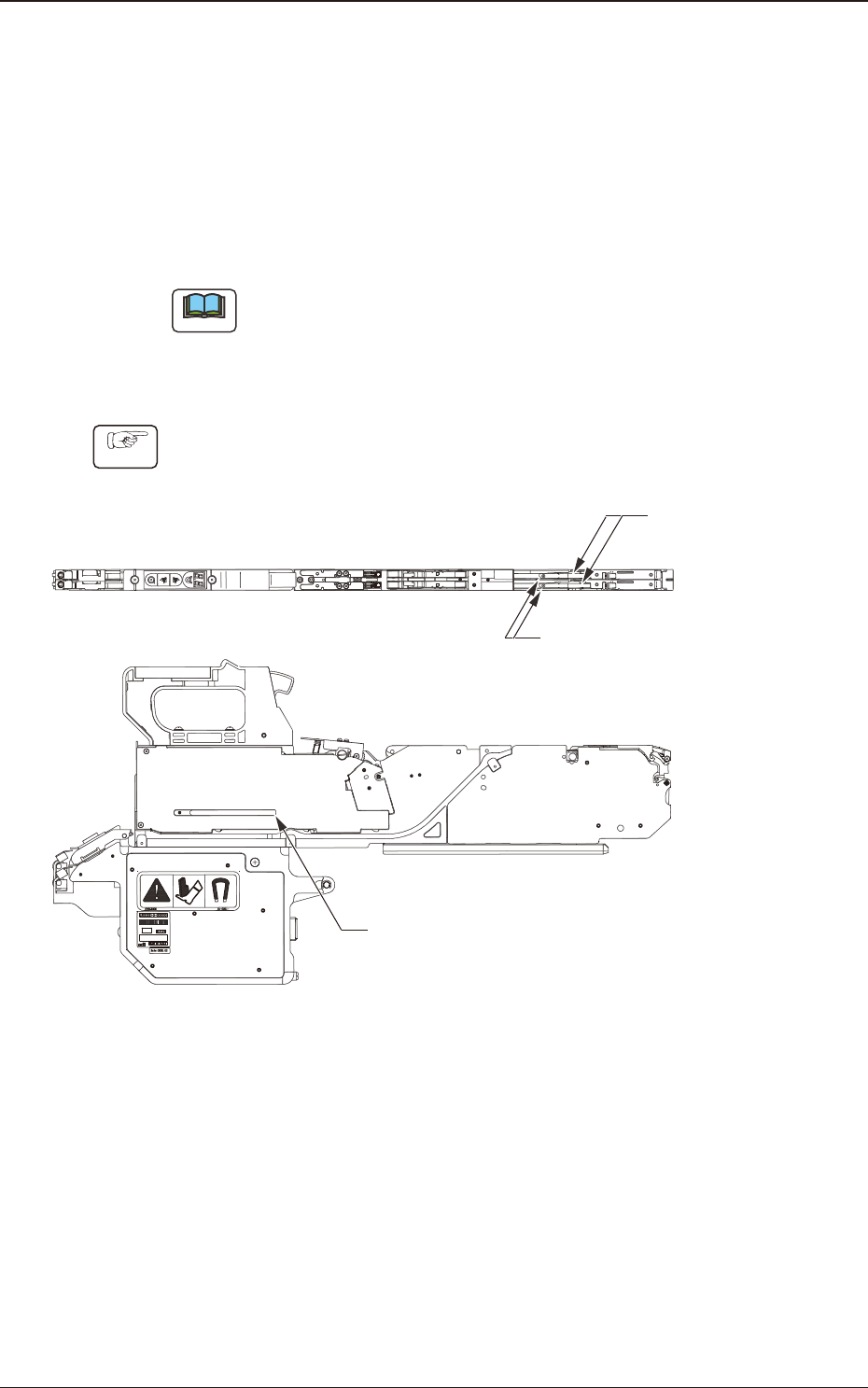
2.6.1 How to remove the Magnetic Plate
Procedure
(1) Loosen the set screw (round head screw) to remove the magnetic plate, and
attach it onto the magnetic plate housing section.
Set Screw
(Round Head Screw)
Magnetic Plate
Magnetic Plate housing section
Fig. B23
1209-001
2.6 Handling of Magnet Plate
OM-1743
2-18