OM-1743-005w.pdf - 第109页
1209-001 7.5.1.4 Left Side Cover #2 Attachment Procedure Procedure (1) Hold the upper side of the Left Side Cover #2 and slide it in the arrow direction to attach. Insert the claw section on the Left Side Cover #2 into t…
1209-001
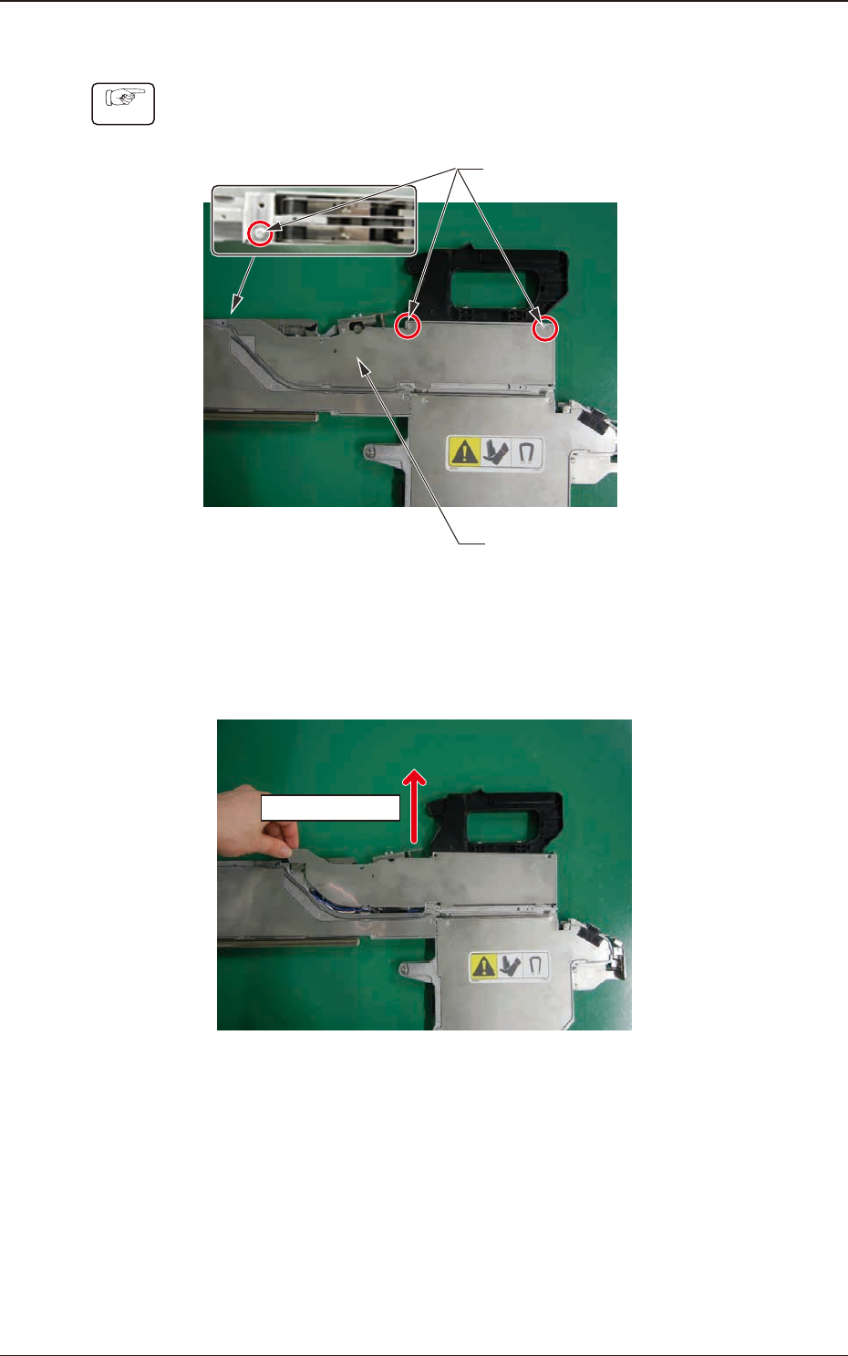
7.5.1.3 Left Side Cover #2 Removal Procedure
Procedure
(1) Remove the three set screws for the Left Side Cover #2.
Left Side Cover #2
Cover Set Screws
Fig. G16
(2) Hold the upper side of the Left Side Cover #2 and slide it in the arrow
direction to remove.
Sliding Direction
Fig. G17
7.5 Maintenance Method
OM-1743
7-14
1209-001
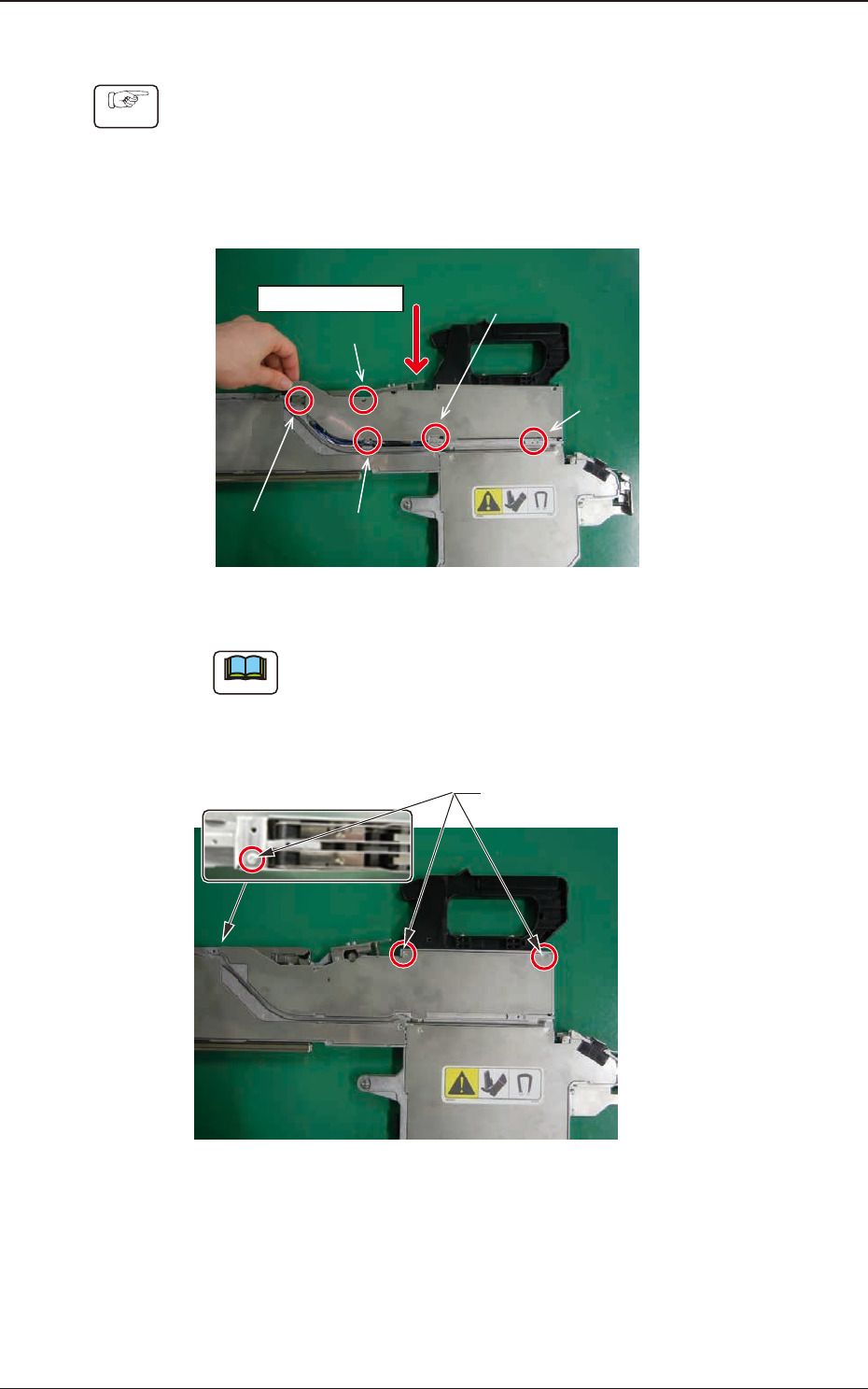
7.5.1.4 Left Side Cover #2 Attachment Procedure
Procedure
(1) Hold the upper side of the Left Side Cover #2 and slide it in the arrow
direction to attach.
Insert the claw section on the Left Side Cover #2 into the slit with the
sequence of 1, 2, 3, 4 and 5 shown in the gure below and slide the cover
while pressing it from above.
Sliding Direction
Step 1
Step 2
Step 4
Step 5
Step 3
Fig. G18
Note
When the cover is attached, take care not to catch any cable.
(2) Fasten the cover set screws and x the Left Side Cover #2.
Cover Set Screws
Fig. G19
7.5 Maintenance Method
OM-1743
7-15
1209-001
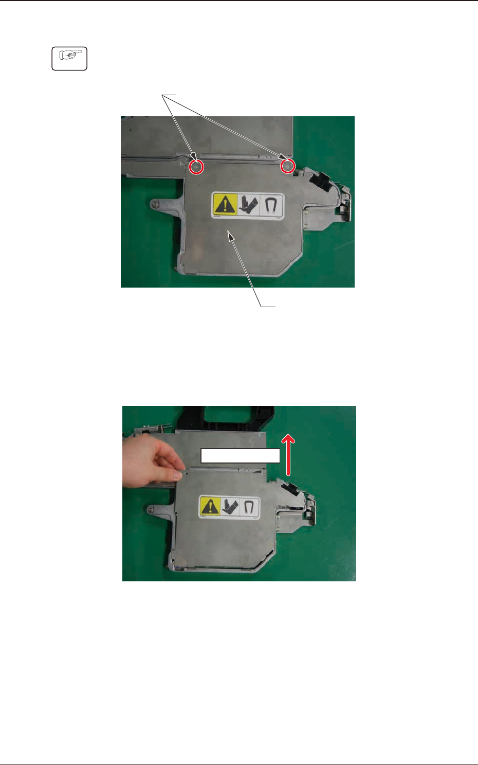
7.5.1.5 PCB BOX Cover Removal Procedure
Procedure
(1) Remove two set screws for the PCB BOX Cover.
PCB BOX Cover
Cover Set Screws
Fig. G20
(2) Hold the upper side of the PBC BOX Cover and slide it in the arrow
direction to remove.
Sliding Direction
Fig. G21
7.5 Maintenance Method
OM-1743
7-16