OM-1743-005w.pdf - 第118页
• Left Sprocket Driving Gear Oiling Procedure Insert the tip of the oiling jig into the oiling port to apply grease to the driving gear located in the sprocket rear (refer to the sectional view). Oiling Jig Oiling Port L…
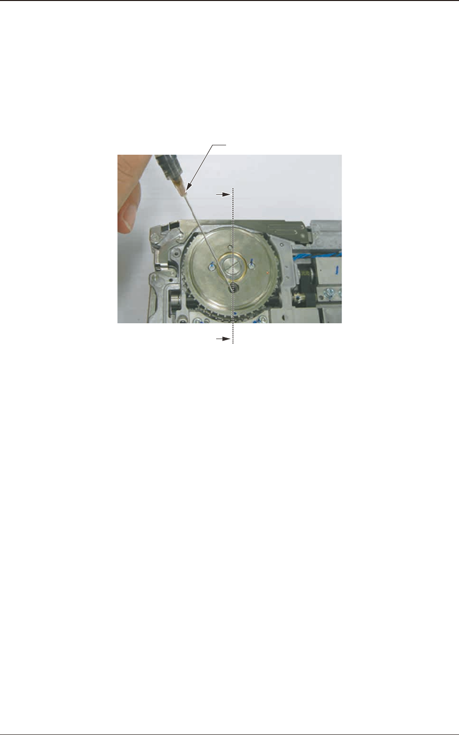
(5) Oiling Work
Using the specially designed oiling jig, apply grease onto the left and right
gears.
The amount of grease to be applied, is about 0.2ml each for right and left
gears (as much as 2 divisions of the jig scale).
When grease has been applied on the left the right gears, turn the sprocket to
smooth the grease entire on the gears.
Oiling Jig
A
A`
Fig. G33
1209-001
7.5 Maintenance Method
OM-1743
7-23
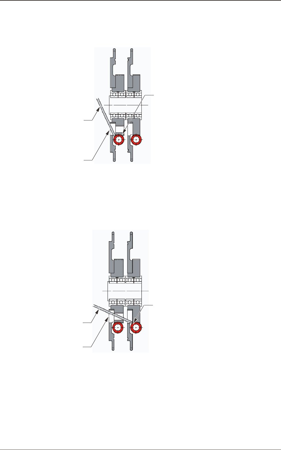
•
Left Sprocket Driving Gear Oiling Procedure
Insert the tip of the oiling jig into the oiling port to apply grease to the driving
gear located in the sprocket rear (refer to the sectional view).
Oiling Jig
Oiling Port
Left Sprocket Driving Gear
Fig. G34 Sprocket Unit Sectional View (A – A’)
•
Right Sprocket Gear Oiling Procedure
Insert the tip of the oiling jig into the oiling port to apply grease to the right
sprocket driving gear located at the back of the screw hole on the left sprocket.
Oiling Jig
Oiling Port
Right Sprocket Driving Gear
Fig. G35 Sprocket Unit Sectional View (A – A’)
(5) When the oiling is completed, fasten the oiling cap securely. When the side
cover is closed, the procedure is completed.
1209-001
7.5 Maintenance Method
OM-1743
7-24
7.5.3 Take-up Gear Unit Greasing Procedure
Procedure
(1) Opening the Left Side Cover #2
Open the Left Side Cover #2 to expose the take-up gear unit.
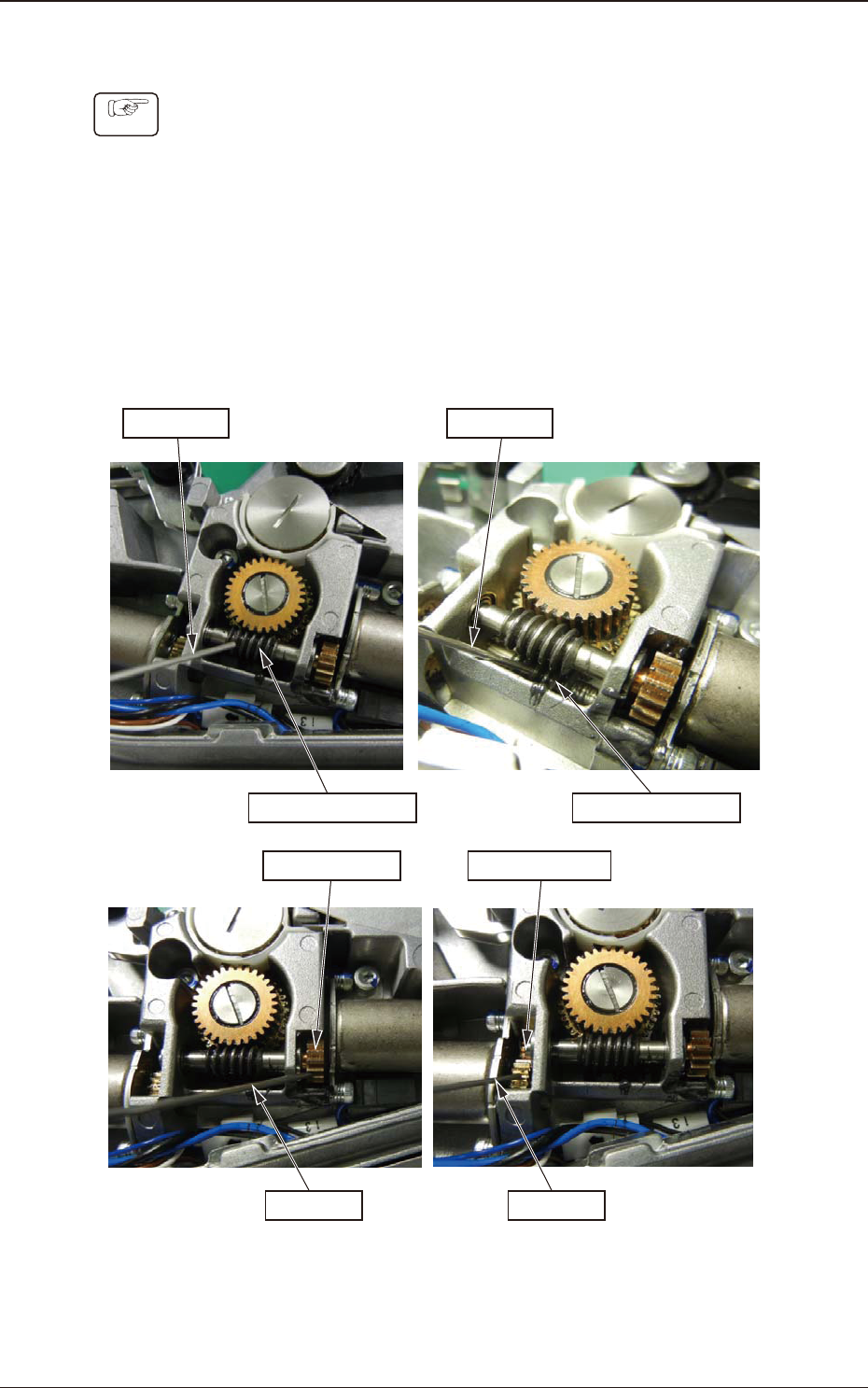
(2) Oiling Work
Using the specially designed oiling jig, apply grease onto the left and right
warm gears, and left and right spur gears.
The amount of grease to be applied, is about 0.2ml each for right and left
warm gears (as much as 2 divisions of the jig scale).
For each of the right and left spur gears, apply about 0.2ml (as much as 2
divisions of the jig scale) of the grease.
Oiling Jig
Left Warm Gear
Oiling Jig
Right Warm Gear
Left Spur Gear
Oiling Jig
Right Spur Gear
Oiling Jig
Fig. G36
(3) Attaching the Left Side Cover #2.
When the Left Side Cover #2 has been attached, the procedure is completed.
1209-001
7.5 Maintenance Method
OM-1743
7-25