西门子SIPLACE S-27 HM用户手册.pdf - 第102页
3 Technical data User Manual SIPLACE S-27 HM 3.10 PCB conveyor Software version SR.503.xx07/2003 US Edition 102 3.10.2.2 T echnical dat a 3 3 Fixed con veyor side Right (standard ), left ( optional) Maximum co mponent he…
User Manual SIPLACE S-27 HM 3 Technical data
Software version SR.503.xx 07/2003 US Edition 3.10 PCB conveyor
101
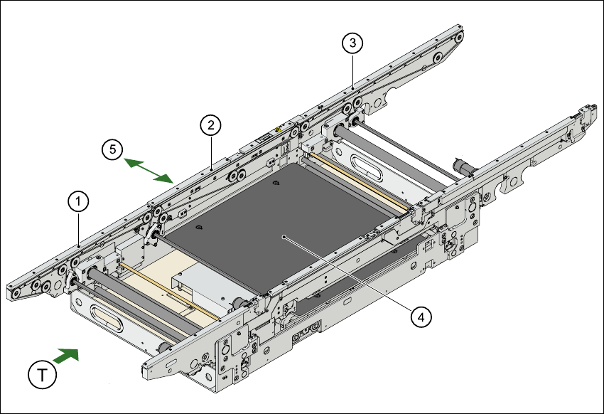
3.10.2 Single conveyor
3.10.2.1 Structure
3
Fig. 3.10 - 1 PCB single conveyor
3
(1) Input conveyor
(2) Center conveyor
(3) Output conveyor
(4) Lifting table
(5) Width adjustment
T Direction of PCB transport

3 Technical data User Manual SIPLACE S-27 HM
3.10 PCB conveyor Software version SR.503.xx07/2003 US Edition
102
3.10.2.2 Technical data
3
3
Fixed conveyor side Right (standard), left (optional)
Maximum component height
6 mm for the 12-segment Collect&Place head
8.5 mm for the 6-segment Collect&Place head
PCB format 50 mm x 50 mm to 508 mm x 460 mm
2" x 2" to 20" x 18"
Long board: up to 610 mm (24"), (option)
PCB thickness 0.5 mm to 4.5 mm
Max. PCB warpage Up: 4.5 mm - PCB thickness
On bottom: 0.3 mm + PCB thickness
Clearance on PCB underside 25 mm (standard), max. 40 mm (option)
PCB transport height 830 mm ± 15 mm (standard)
900 mm ± 15 mm (optional)
930 mm ± 15 mm (optional)
950 mm ± 15 mm (SMEMA: optional)
Type of interface Siemens (standard), (SMEMA optional)
Component-free PCB handling edge 3 mm
PCB changeover time 2.5 s
Bad fiducial detection Possible
Automatic width adjustment Possible
User Manual SIPLACE S-27 HM 3 Technical data
Software version SR.503.xx 07/2003 US Edition 3.10 PCB conveyor
103
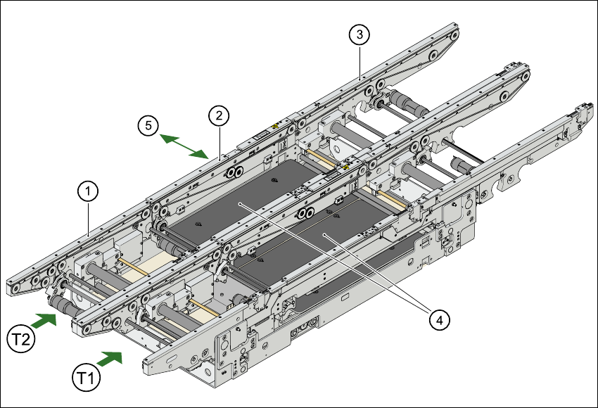
3.10.3 Dual conveyor
3.10.3.1 Structure
3
Fig. 3.10 - 2 PCB conveyor - dual conveyor
(1) Input conveyor
(2) Center conveyor
(3) Output conveyor
(4) Lifting table
(5) Width adjustment
T1 Conveyor track 1
T2 Conveyor track 2