西门子SIPLACE S-27 HM用户手册.pdf - 第188页
7 Station extensions User Manual S IPLACE S-27 H M 7.6 Fine calibration Software version SR.503.xx07/2003 US Edition 188 7.6.6 Displaying a nd analyzing meas ured values The meas ured v alues can be di splaye d graphi ca…
User Manual SIPLACE S-27 HM 7 Station extensions
Software version SR.503.xx 07/2003 US Edition 7.6 Fine calibration
187
7.6.4 Description of the functions
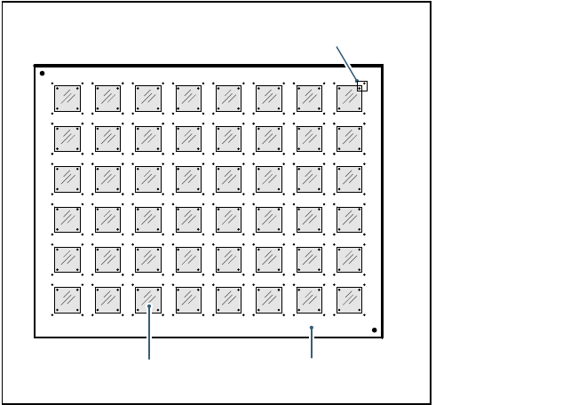
A large number of CERAM components are placed on a glass PCB covered with adhesive film.
On the top of the CERAM components there are reference fiducials in each corner. The glass
PCB also has reference fiducials in the immediate vicinity of these component fiducials.
Fig. 7.6 - 1 Fine calibration principle
Immediately after placement, the PCB camera takes four sets of images of the associated refer-
ence fiducials on both PCB and component. The analysis program is then used to determine the
placement offset in the X/Y direction and the angular deviation. The offset values are used to cal-
culate the corrected values, which are then entered in the machine data (FK_off.ma).
7.6.5 Measuring modes
The following measurement modes can be selected:
– Measure the values for an individual placement head.
– Measure the values for all the placement heads in a placement area.
– Measure the values for the entire machine.
The measurement can be repeated as often as required, with or without replacing the CERAM
components.
Glass components Glass PCB
Field of view of the PCB camera
7 Station extensions User Manual SIPLACE S-27 HM
7.6 Fine calibration Software version SR.503.xx07/2003 US Edition
188
7.6.6 Displaying and analyzing measured values
The measured values can be displayed graphically on screen and saved to diskette. The following
display options are available:
– Display measured values for each individual placement head.
– Display the measured values for each segment.
– Display measured values for the X or Y direction or angular measurement.

User Manual SIPLACE S-27 HM 7 Station extensions
Software version SR.503.xx 07/2003 US Edition 7.7 Nozzle changer for the 6-segment Collect&Place head
189
7.7 Nozzle changer for the 6-segment Collect&Place
head
7.7.1 Overview
The placement system is supplied as standard with two Collect&Place heads. As an option, a
nozzle changer can be installed for each Collect&Place head. This enables the nozzle configura-
tion to be changed quickly, thus allowing the Collect&Place head to be quickly adapted to the
needs of the placement process.
The nozzle changer consists of at least one, and up to five magazines, each with twelve nozzle
garages (see Fig. 7.7 - 1
). The magazines are seated on a common support. Each magazine is
centered using two parallel pins and fixed in place with a spring hook.
Magazines for the 9xx and 8xx nozzle types can be set up. The magazines can be arranged as
required.
PLEASE NOTE: 7
Please refer to Section 7.1
on page 161 for information on the nozzle changer for the 12-segment
Collect&Place head. 7
7.7.2 Technical data
7
Nozzle changer for the 6-segment Collect&Place head
Dimensions (length x width x height) 282 mm x 233 mm x 108 mm
Number of nozzle garages Min. 6 / max. 30
Nozzle types 8 xx, 9 xx
Time required to open and close the locking plate < 200 ms
Capacity of the reject bin Approx. 50 nozzles from the 9xx type,
Approx. 5 nozzles from the 8xx type
Pneumatic system Compressed air line 0.53 MPa (5.3 bar)