西门子SIPLACE S-27 HM用户手册.pdf - 第40页
2 Operational safety User Manual SIPLACE S-27 HM 2.3 Laser classif ication Software version SR.503.xx07/2003 US Edition 40 2.3.3 Lase r class 2 The foll owing modu les a re assign ed to la ser cl ass 2: – Las er light ba…
User Manual SIPLACE S-27 HM 2 Operational safety
Software version SR.503.xx 07/2003 US Edition 2.3 Laser classification
39
2.3 Laser classification
2.3.1 Laser class 1
2.3.1.1 Classification of the whole machine
2
PLEASE NOTE: 2
Modules in laser classes 1 and 1M are not identified.
2.3.1.2 Classification of the camera systems
2
2.3.2 Laser class 1M
Do not look directly at this with optical instruments!
2
2
All installed camera systems and the whole machine when ready for
operation are assigned to laser class 1.
The laser classes are determined according to DIN EN 60825-1:2001.
2
The following camera systems are assigned to laser class 1:
– Multicolor PCB camera (type 18) 21
2
The following camera systems are assigned to laser class 1M:
– 24 x 24 component camera on the 12-segment Collect&Place head
– 39 x 39 component camera on the 6-segment Collect&Place head
– 16 x 16 DCA camera on the 6-segment or 12-segment Collect&Place head

2 Operational safety User Manual SIPLACE S-27 HM
2.3 Laser classification Software version SR.503.xx07/2003 US Edition
40
2.3.3 Laser class 2
The following modules are assigned to laser class 2:
– Laser light barrier, placement area 1 in the PCB conveyor
– Laser light barrier, placement area 2 in the PCB conveyor
– PCB barcode scanner
2
2
Laser radiation
Do not look into beam!
User Manual SIPLACE S-27 HM 2 Operational safety
Software version SR.503.xx 07/2003 US Edition 2.4 Safety instructions for operating the machine
41
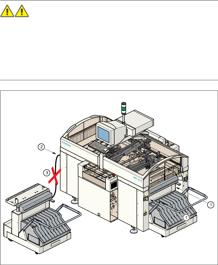
2.4 Safety instructions for operating the machine
2.4.1 Safety instructions for docking and undocking the component trolley
WARNING 2
Æ Never reach into the gap between the component trolley and the machine base (item 1).
Æ Always check that the component trolley is docked on the placement system before connecting
or disconnecting the power cable for the component trolley at the socket on the placement sys-
tem (item 2).
Æ NEVER connect the connecting cable for the component trolley to the socket on the placement
system and then operate the component trolley outside the machine via the compressed air
control unit (item 3).
Fig. 2.4 - 1 Safety instructions on the component trolley