西门子SIPLACE S-27 HM用户手册.pdf - 第153页
User Manual SIPLAC E S-27 HM 6 Component han dling Software version SR.503.xx 07/2003 US Edition 6.6 Matrix tray changer 153 6.6 Matrix tra y changer 6.6. 1 Ove rview Fig. 6.6 - 1 M atrix tray changer , back view (1) Mai…
6 Component handling User Manual SIPLACE S-27 HM
6.5 Used tape cutter Software version SR.503.xx07/2003 US Edition
152
PLEASE NOTE
On SIPLACE automatic placement systems, only use the tape feeders specified for these ma-
chines. The used tape channel which removes the used tape is located upstream of the feeders.6
Æ Insert the tape into the feeder as described in the corresponding section.
Æ Guide the used tape into the used tape channel of the cutter as described in Fig. 6.5 - 2
The used tape guide channels are located upstream of the feeders. They are positioned directly
above the used tape cutters.
The tape is automatically guided through the used tape guide channel into the used tape cutter
below. There, the tape is shredded by the pneumatically-actuated cutting blade. The waste tape
then passes via the waste tape chute into the waste container of the component trolley.
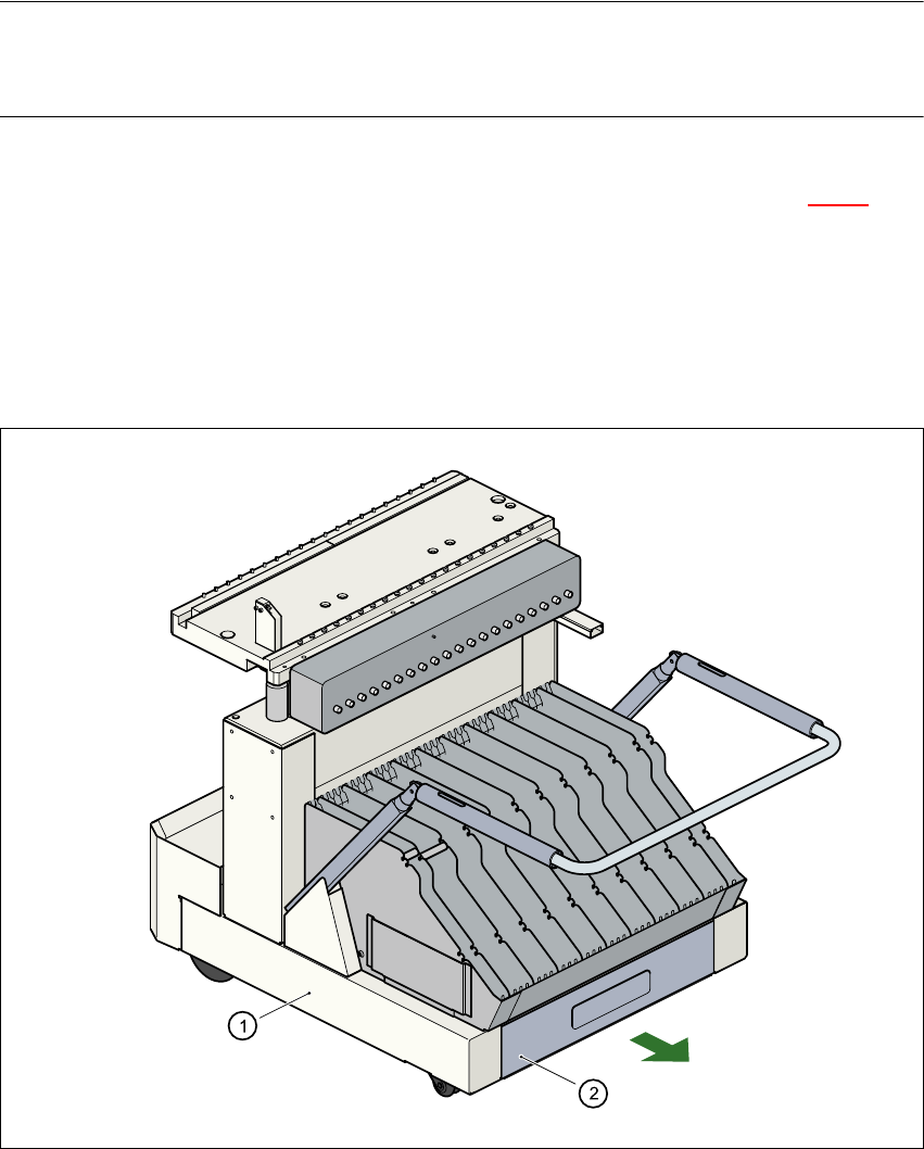
Fig. 6.5 - 3 Pull-out waste tape container in the component trolley
6
(1) Component trolley
(2) Waste tape container, extendible
User Manual SIPLACE S-27 HM 6 Component handling
Software version SR.503.xx 07/2003 US Edition 6.6 Matrix tray changer
153
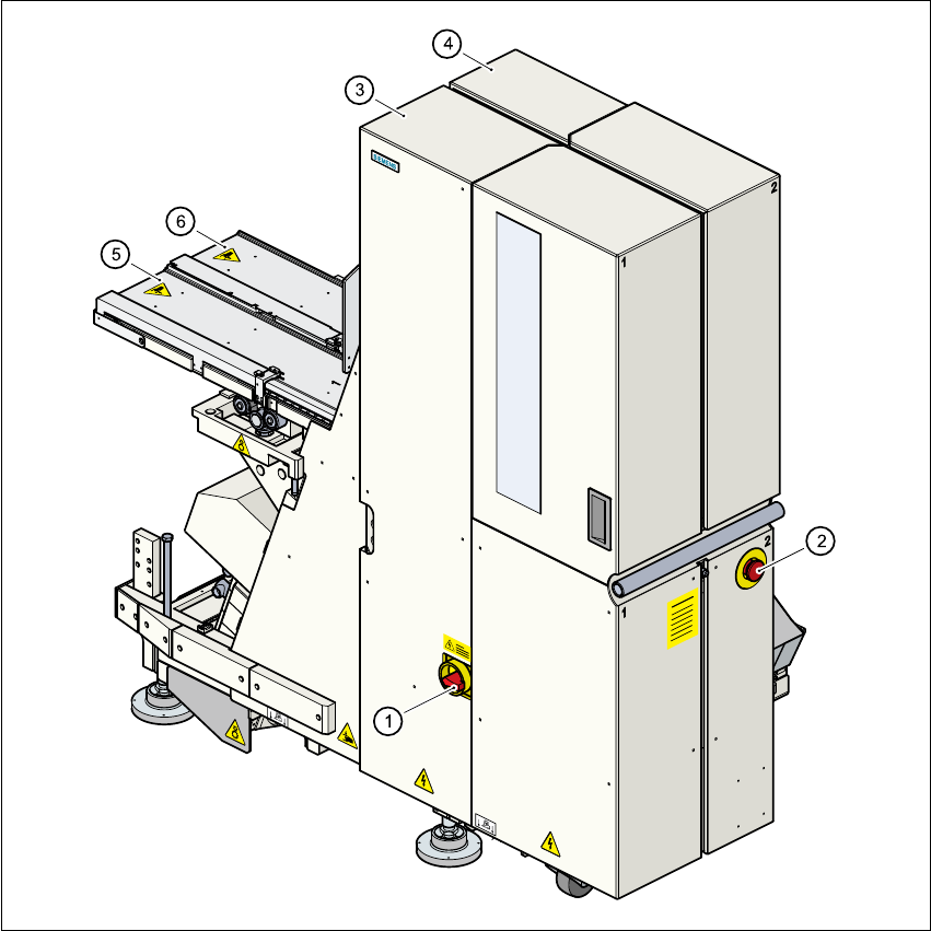
6.6 Matrix tray changer
6.6.1 Overview
Fig. 6.6 - 1 Matrix tray changer, back view
(1) Main power switch
(2) Emergency stop button
(3) Tower 1 for up to 40 waffle trays
(4) Tower 2 for up to 40 waffle trays
(5) Feed axis 1
(6) Feed axis 2

6 Component handling User Manual SIPLACE S-27 HM
6.6 Matrix tray changer Software version SR.503.xx07/2003 US Edition
154
6.6.2 General
The use of flatpack ICs is becoming an increasingly significant aspect in the production of flat
modules. These components are now almost exclusively provided in waffle trays.
The space required by waffle trays is relatively large in comparison to the component density,
however.
The low component capacity also requires the waffle trays to be changed frequently, which
means that the placement sequence has to be interrupted if the trays are changed manually.
The use of a matrix tray changer eliminates this unnecessary time loss since the waffle trays are
stored and automatically changed. Programmable, random access to up to 2 x 40 waffle trays
also increases the range of components that can be made available.
PLEASE NOTE: 6
The matrix tray changer can be coupled at location 1 on the right-hand side of the machine and/
or at location 3 on the left-hand side of the machine. It does not take up the whole width of a lo-
cation. The component feeder table integrated into the matrix tray changer (see item 2 in Fig. 6.6
- 2) has a capacity of 9 feeder locations. 6