西门子SIPLACE S-27 HM用户手册.pdf - 第92页
3 Technical data User Manual SIPLACE S-27 HM 3.8 Placement heads Software version SR.503.xx07/2003 US Edition 92 3.8.1.1 Descri ption – The 12- segm ent C olle ct&Pl ace h ead w orks u sing t he "c ollec t &…
User Manual SIPLACE S-27 HM 3 Technical data
Software version SR.503.xx 07/2003 US Edition 3.8 Placement heads
91
3
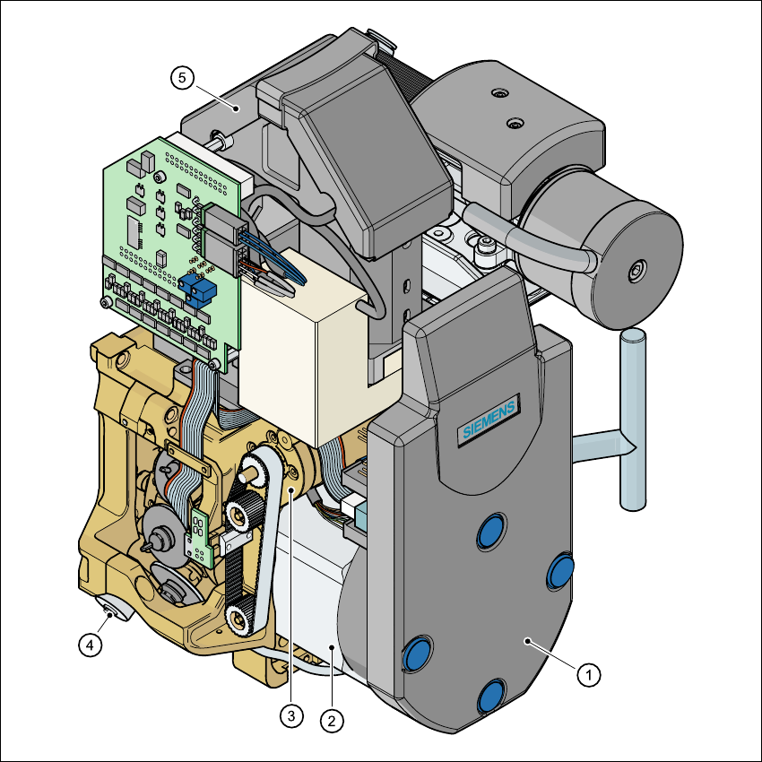
Fig. 3.8 - 2 12-segment Collect&Place head - Function groups, part 2
3
(1)Intermediate distributor board (beneath the cover)
(2)Star drive - DR motor
(3)Z axis motor
(4)Valve adjustment drive
(5)24 x 24 component camera

3 Technical data User Manual SIPLACE S-27 HM
3.8 Placement heads Software version SR.503.xx07/2003 US Edition
92
3.8.1.1 Description
– The 12-segment Collect&Place head works using the "collect & place" principle, i.e. the com-
ponents are held by the nozzles with the aid of a vacuum and, after one complete pick-up cycle,
are placed gently and accurately on the PCB with the aid of forced air. The vacuum in the noz-
zles is also checked several times to determine whether the components were picked up and
set down correctly.
– The "adaptive" sensor stop mode of the z axis compensates for any irregularity of the PCB sur-
face when the components are set down.
– All the components are inserted with the same cycle time. Before the component is inserted, it
is measured by the optoelectronic vision module.
– The component camera creates an image of the current component.
– The precise position of the component is also determined.
– The package form of the current component is compared against the programmed package
form in order to identify it. Any components that cannot be identified are rejected.
– The turning station turns the component to the required placement position.
– Defective components are rejected and are picked up again during a repair run.
3.8.1.2 Technical data
3
Component range 0201 to PLCC44, including BGA, µBGA, flip-chip,
TSOP, QFP, PLCC, SO to SO32, DRAM
Component specification
Max. height
Min. lead pitch
Min. bump pitch
Min. ball/bump diameter
Min. dimensions
Max. dimensions
Max. weight
6 mm (10.7 mm available upon request)
0.5 mm
0.35 mm
0.2 mm
0.6 mm x 0.3 mm
18.7 mm x 18.7 mm
2 g
Programmable set-down force 2.4 to 5.0 N
Max. placement rate 13.250 comp/h
Nozzle types 9 xx
Angular accuracy ± 0.7° / 4 sigma
Placement accuracy ± 90 µm / 4 sigma
User Manual SIPLACE S-27 HM 3 Technical data
Software version SR.503.xx 07/2003 US Edition 3.8 Placement heads
93
3.8.2 6-segment Collect&Place head with standard component camera
3
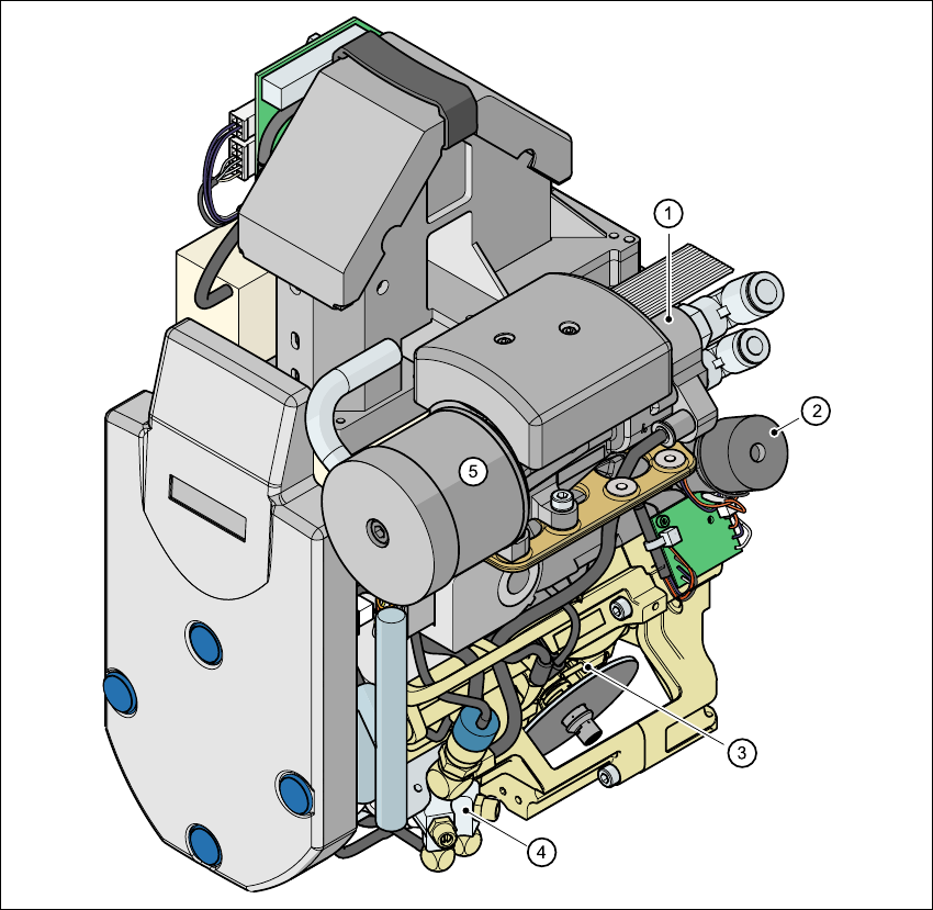
Fig. 3.8 - 3 6-segment Collect&Place head - Function groups, part 1
3
(1)Vacuum generator
(2)Turning station, DP axis
(3)Star with 6 sleeves, DR axis
(4)Forced air valve
(5)Silencer