西门子SIPLACE S-27 HM用户手册.pdf - 第198页
7 Station extensions User Manual S IPLACE S-27 H M 7.8 DCA camer a on the 12-se gment Collect&Place h ead Software version SR.503.xx07/2003 US Edition 198 7.8.1 Description With the DCA camer a, the 12-seg ment Co ll…
User Manual SIPLACE S-27 HM 7 Station extensions
Software version SR.503.xx 07/2003 US Edition 7.8 DCA camera on the 12-segment Collect&Place head
197
7.8 DCA camera on the 12-segment Collect&Place
head
7
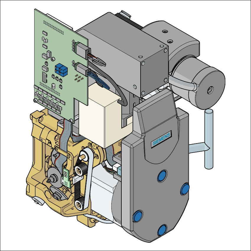
Fig. 7.8 - 1 DCA camera on the 12-segment Collect&Place head
7
(1) DCA camera
(2) 12-segment Collect&Place head

7 Station extensions User Manual SIPLACE S-27 HM
7.8 DCA camera on the 12-segment Collect&Place head Software version SR.503.xx07/2003 US Edition
198
7.8.1 Description
With the DCA camera, the 12-segment Collect&Place head is able to optically center and place
components of the order of magnitude of 0.6 mm x 0.3 mm to 13 mm x 13 mm. The DCA pack-
age optimizes the speed and accuracy when placing high-speed flip chips and bare die compo-
nents.
7.8.2 Technical data
Component range 0201 to 13 mm x 13 mm
Component specification
Max. height
Min. lead pitch
Min. bump pitch
Min. ball/bump diameter
Min. dimensions
Max. dimensions
Max. weight
6 mm
0.4 mm
0.2 mm
0.11 mm
0.6 mm x 0.3 mm
13 mm x 13 mm
2 g
Programmable set-down force 2.4 to 5.0 N
Nozzle types 9 xx
Max. placement rate 13,250 comp/h
Angular accuracy ± 0.7° / 4 sigma
Placement accuracy ± 90 µm / 4 sigma
User Manual SIPLACE S-27 HM 7 Station extensions
Software version SR.503.xx 07/2003 US Edition 7.9 DCA camera
199
7.9 DCA camera
7.9.1 Structure
7
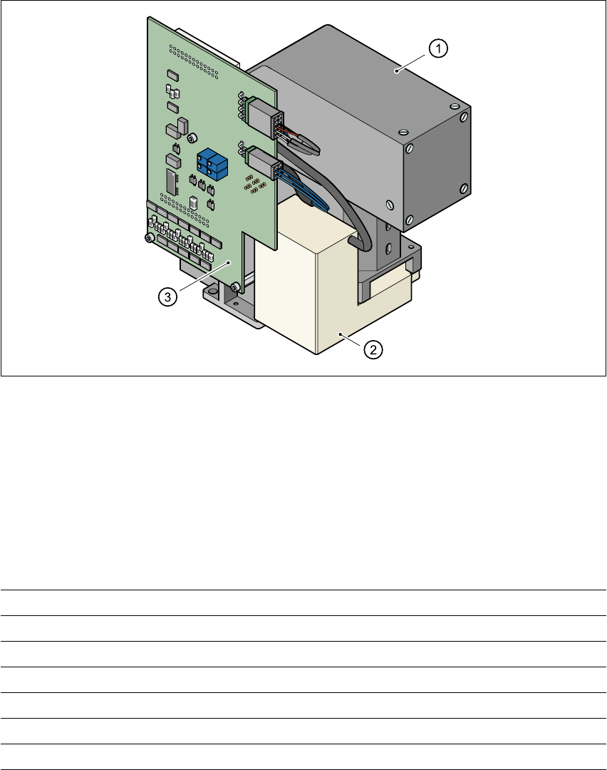
Fig. 7.9 - 1 DCA camera
7
(1) DCA camera, lens and illumination
(2) Camera amplifier
(3) Illumination control
7
7.9.2 Technical data
7
7
Component dimensions 0.6 mm x 0.3 mm to 13 mm x 13 mm
Range of components 0201 up to 13 mm x 13 mm, flip-chip, bare die
Min. lead pitch 0.4 mm
Minimum bump pitch 0.2 mm
Min. ball/bump diameter 0.11 mm
Field of vision 15.7 mm x 15.7 mm
Method of illumination Front lighting (four levels programmable as required)