西门子SIPLACE S-27 HM用户手册.pdf - 第148页
6 Component handling User Manual SIPLACE S-27 HM 6.4 Component trolley Software version SR. 503.xx07/2003 US Edition 148 6 Fig. 6.4 - 4 Connecting the compressed air supply for bulk case feeders (1) Coupli ng plug fo r c…
User Manual SIPLACE S-27 HM 6 Component handling
Software version SR.503.xx 07/2003 US Edition 6.4 Component trolley
147
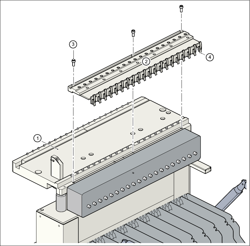
6.4.3 Compressed air supply for bulk case feeder
Bulk case feeders require compressed air to operate. We therefore offer a compressed air supply
for bulk case feeders as an optional extra.
It is easy to fit. The compressed air supply (item 2) is fixed to the component feeder table (item 1)
using three screws DIN 912, M8x20 (Pos. 3). The compressed air supply has retaining clips (item
4) on the back. These secure the bulk case feeder to the component trolley and ensure that the
compressed air supply is working properly.
6
Fig. 6.4 - 3 Compressed air supply for bulk case feeders
(1) Component feeder table
(2) Compressed air supply for bulk case feeders
(3) Screw DIN 912, M8x20
(4) Retaining clamp
6 Component handling User Manual SIPLACE S-27 HM
6.4 Component trolley Software version SR.503.xx07/2003 US Edition
148
6
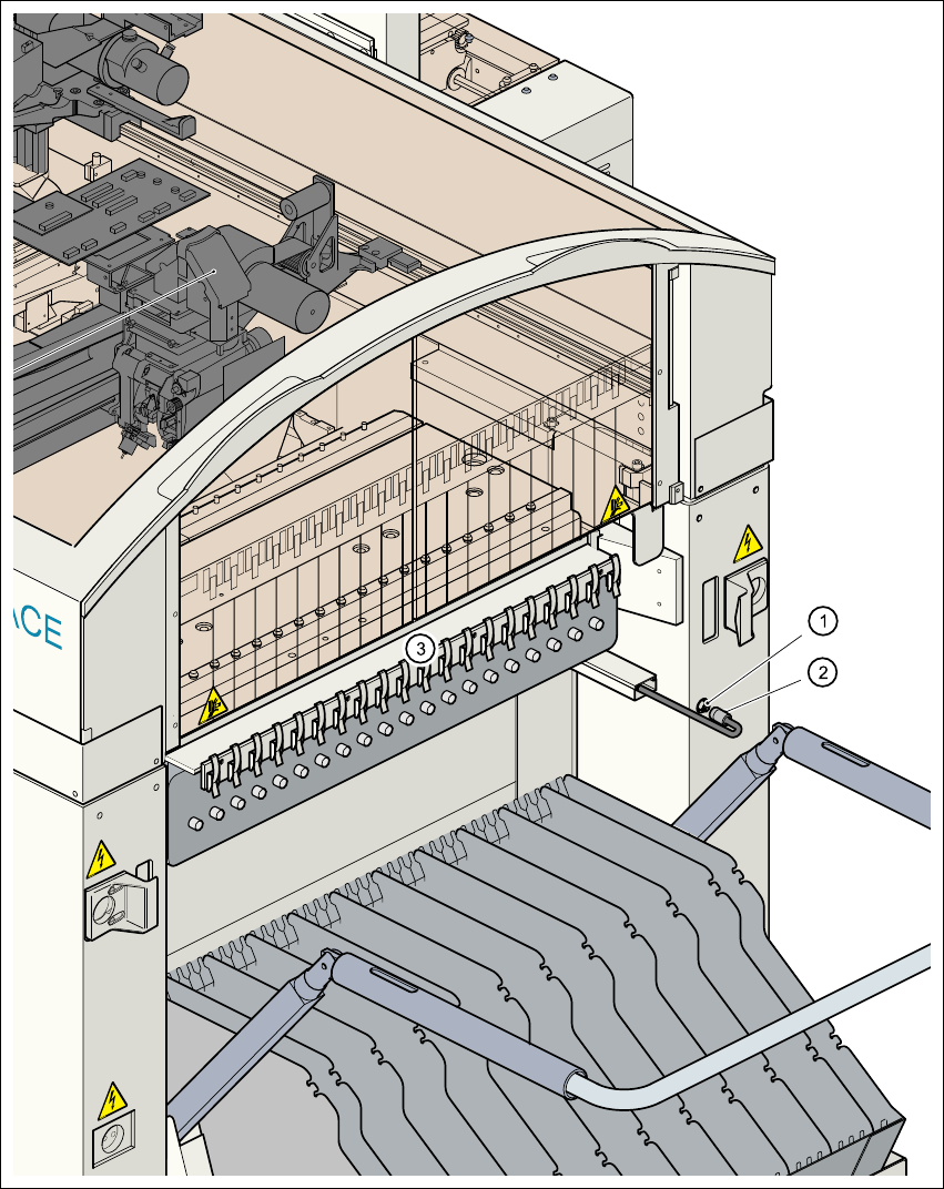
Fig. 6.4 - 4 Connecting the compressed air supply for bulk case feeders
(1) Coupling plug for compressed air
(2) Coupling socket with supply hose
(3) Compressed air distributor for bulk case feeders
User Manual SIPLACE S-27 HM 6 Component handling
Software version SR.503.xx 07/2003 US Edition 6.4 Component trolley
149
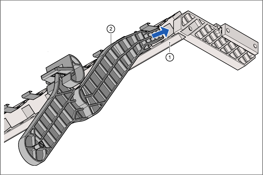
6.4.4 Support for the middle tape reel for 3 x 8 mm feeders
Type 3 x 8 mm S feeders transport components to the pick-up position on three tracks. The tape
reels for the two outer tracks are located between the dividing plates in the tape container. The
middle tape reel is arranged over the tape reels for the two outer tracks.
For the middle tape reels you will therefore also need:
– 1 adapter plate for holding the tape reel holder (item 1) and
– 1 tape reel holder (item 2) for every two feeders
The adapter plate is fixed to the component trolley with four fillister head screws, and the tape
reel holders are inserted into the square openings in the adapter plate.
Fig. 6.4 - 5 Support for the middle tape reel for 3 x 8 mm feeders
(1) Adapter plate
(2) Tape reel holder