西门子SIPLACE S-27 HM用户手册.pdf - 第97页
User Manual SIPLAC E S-27 HM 3 Technical data Software vers ion SR.503.xx 07/2003 US Edition 3.9 Vision m odules 97 3.9.2 Component camera (24 x 24) on the 12-segment Co llect&Place head 3.9.2.1 Str ucture 3 Fig. 3.9…
3 Technical data User Manual SIPLACE S-27 HM
3.9 Vision modules Software version SR.503.xx07/2003 US Edition
96
3.9 Vision modules
3.9.1 Description
Each placement system has
– two component cameras on the placement heads and
– two PCB cameras on the underside of the X axis gantries.
The vision analysis unit is located in the control unit for the placement system. The component
vision module is used to determine:
– the precise position of the components at the nozzle and
– the geometry of the package form.
The PCB vision module uses fiducials on the PCBs to determine:
– the position of the PCB,
– its rotation angle
– and the PCB skew.
The PCB vision module also uses fiducials on the feeder modules to determine the exact pick-up
position of components. This is particularly important for small components.
User Manual SIPLACE S-27 HM 3 Technical data
Software version SR.503.xx 07/2003 US Edition 3.9 Vision modules
97
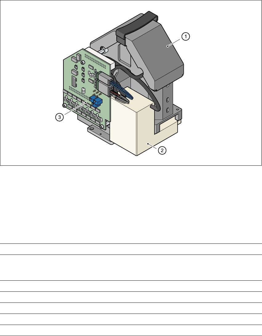
3.9.2 Component camera (24 x 24) on the 12-segment Collect&Place head
3.9.2.1 Structure
3
Fig. 3.9 - 1 Component camera (24 x 24) on the 12-segment Collect&Place head
(1) Component camera, lens and illumination
(2) Camera amplifier
(3) Illumination control
3.9.2.2 Technical data
3
Max. component dimensions 0.6 mm x 0.3 mm to 18.7 mm x 18.7 mm
Range of components 0201 to PLCC44
including BGA, µBGA, flip-chip, TSOP, QFP
PLCC, SO to SO32, DRAM
Min. lead pitch 0.5 mm
Minimum bump pitch 0.35 mm
Min. ball/bump diameter 0.2 mm
Field of vision 24 mm x 24 mm
Method of illumination Front-lighting (3 levels programable as required)
3 Technical data User Manual SIPLACE S-27 HM
3.9 Vision modules Software version SR.503.xx07/2003 US Edition
98
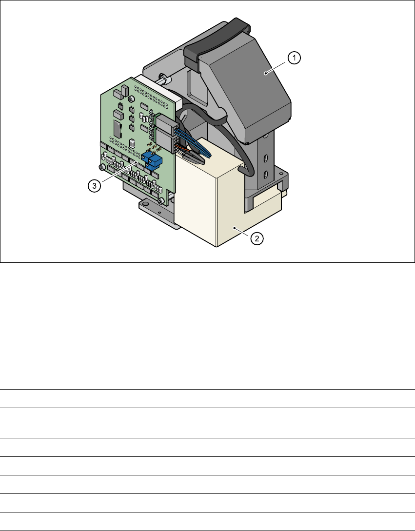
3.9.3 Component camera (39 x 39) on the 6-segment Collect&Place head
3.9.3.1 Structure
3
Fig. 3.9 - 2 Component camera (39 x 39) on the 6-segment Collect&Place head
3
(1) Component camera, lens and illumination
(2) Camera amplifier
(3) Illumination control
3.9.3.2 Technical data
3
Component dimensions 1.6 mm x 0.8 mm to 32 mm x 32 mm
Range of components 0603 to 32 mm x 32 mm
PLCC, SO, QFP, TSDP, SOT, MELF, CHIP, IC BGA
Min. lead pitch 0.5 mm
Minimum bump pitch 0.56 mm
Min. ball/bump pitch 0.32 mm
Field of vision 39 mm x 39 mm
Method of illumination Front lighting (3 levels programmable as required)