西门子SIPLACE S-27 HM用户手册.pdf - 第170页
7 Station extensions User Manual S IPLACE S-27 H M 7.2 Component barc ode reader Software version SR.503.xx07/2003 US Edition 170 Track alloc ation Four-dig it barco de strips ar e attached to th e lateral safety sc reen…
User Manual SIPLACE S-27 HM 7 Station extensions
Software version SR.503.xx 07/2003 US Edition 7.2 Component barcode reader
169
7.2 Component barcode reader
7.2.1 General
With the placement system, a barcode reader can be used to check that the track allocation is
correct and to read component data from component reels.
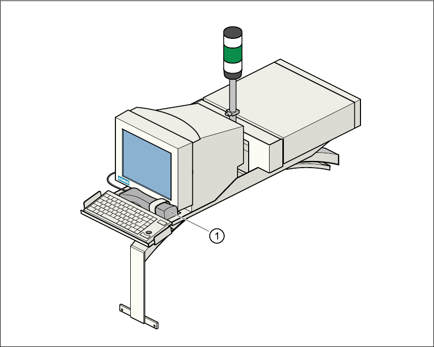
Fig. 7.2 - 1 Component barcode reader
(1) Component barcode reader

7 Station extensions User Manual SIPLACE S-27 HM
7.2 Component barcode reader Software version SR.503.xx07/2003 US Edition
170
Track allocation
Four-digit barcode strips are attached to the lateral safety screens for the purposes of track allo-
cation. The first digit is used to identify the component table (1 or 2), while the remaining three
digits specify the track number. There are also return barcodes at both ends of the barcode strip.
The barcode strips are numbered consecutively in intervals of two (1, 3, 5, 7...) and each repre-
sents 2 tracks (barcode 1 = track 1 and 2).
Components
Data can be read from the component reels to compare the stock of components against the
quantity specified in the set-up file (refill check), for example.
An audible signal is given when each dataset has been read successfully.
PLEASE NOTE 7
The component barcode reader option must be configured on the line computer or the SIPLACE
Pro.
Barcodes that start with the number 1 or 2 and are 5 digits long are interpreted as track barcodes.
All other barcodes that do not start with number 1 or 2 are regarded as component barcodes. 7
7.2.2 Technical data
7
Connection Station computer
Data entry Via barcode scanner or keyboard
Number of characters Up to 40
Not permissible Barcodes starting with a 1 or 2 and less than 5
characters long
Number of barcodes Up to 6 per component
Filter for suppressing data Up to 1 per barcode
Preset code types Code 39 (standard or ASCII)
Code 2 of 5, interleaved and normal,
Code 128, UPC/EAN/JAN codes
(others available upon request)
User Manual SIPLACE S-27 HM 7 Station extensions
Software version SR.503.xx 07/2003 US Edition 7.3 Dual conveyor
171
7.3 Dual conveyor
7.3.1 Structure of the dual conveyor
The conveyor belts are driven by DC motors. There is a lifting table for holding the PCBs in each
processing area. The width of the PCB conveyor can be adjusted either via the menu or using
the line computer.
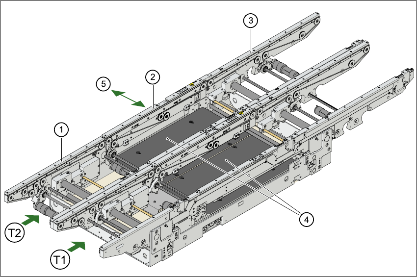
Fig. 7.3 - 1 Structure of the dual conveyor
7.3.2 General
As the name suggests, the dual conveyor has two transport tracks, which are electrically and
mechanically independent of one another. In the Standard version, the right-hand side is the
fixed side. There is another version, however, in which the left-hand side is the fixed side.
There are two conveyor modes: "Single conveyor" and "Dual conveyor asynchronous. Enter the
conveyor mode you wish to use in the machine data (konfig.ma).
(1) Input conveyor (2) Center conveyor
(3) Output conveyor (4) Lifting table
(5) Width adjustment
T1 Conveyor track 1
T2 Conveyor track 2