西门子SIPLACE S-27 HM用户手册.pdf - 第106页
4 Setting up t he placement machine User Manual SIPLACE S-27 H M 4.1 Transport dimens ions Software version SR.503.xx07/2003 US Edition 106 4.1.1 T ransport configurat ion and transport ation The foll owing compon ents a…
User Manual SIPLACE S-27 HM 4 Setting up the placement machine
Software version SR.503.xx 07/2003 US Edition 4.1 Transport dimensions
105
4 Setting up the placement machine
4.1 Transport dimensions
4
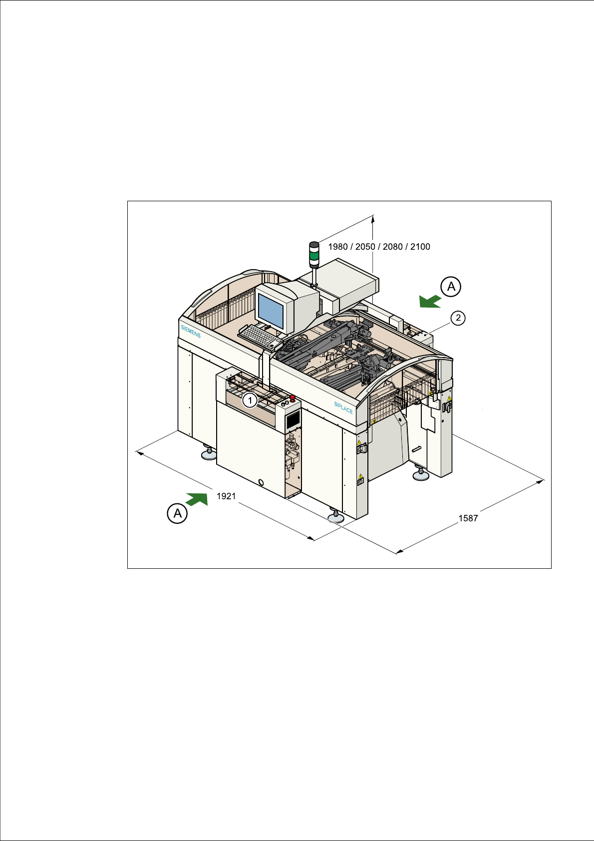
Fig. 4.1 - 1 Dimensions of the placement machine during transportation and setting up
4
(A) Points for attaching the fork-lift truck (fork length 1600 mm)
(1) Input conveyor
(2) Output conveyor
4
The standard PCB conveyor height is 830 mm 15 mm. The standard overall height of the
machine is 1980 mm. For a PCB conveyor height of 950 mm (SMEMA option), this gives an
overall height of 2100 mm.

4 Setting up the placement machine User Manual SIPLACE S-27 HM
4.1 Transport dimensions Software version SR.503.xx07/2003 US Edition
106
4.1.1 Transport configuration and transportation
The following components are not installed when the placement machine is delivered from the
factory:
– Keyboards
–Monitors
– Fault indicator lamp and
– Component trolley
Æ Install the dismantled components for commissioning.
Æ Use a fork-lift truck to transport the placement machine with a minimum fork length of
1600 mm.
Æ Attach the fork-lift truck only at the indicated points.
4.1.2 Quality of the foundation
Æ Ensure that
– you set up the placement machine on a firm and non-vibrating foundation.
– the load bearing capacity per unit area of the foundation is greater than 1000 kg/m².
4.1.3 Compressed air supply
– The pressure of the compressed air supply must be 0.55 MPa (5.5 bar) min. The maximum
permitted value is 0.8 MPa (8 bar).
– The compressed air must conform to the specification (see Section 3.4
from page 80).
This can be achieved with
– oil-free compressors, e.g. Atlas, Copco type ZR4
– compressed air washer/driers
– micro-filters, series X, e.g. from Zander
4.1.4 Main power supply
– The power socket must be fused. The fuse ratings are:
3 x 16 A for 3 x 400 VAC / 3 x 208 VAC/3 x 200 VAC 4
User Manual SIPLACE S-27 HM 4 Setting up the placement machine
Software version SR.503.xx 07/2003 US Edition 4.2 Setting up the placement machine
107
4.2 Setting up the placement machine
Æ Raise the placement machine using the fork-lift truck, and adjust the feet until there is a gap of
830 mm between the top edge of the PCB conveyor and the bottom edge of the feet.
Æ Leave a gap of 1 to 3 mm between the PCB conveyors of the placement machine.
Æ Align all the placement machines exactly in line with one another. Use a cord pulled tight to
ensure this.
Æ Adjust each placement machine using a spirit level with an accuracy of 0.02 mm/m.
Æ Lock the feet in position.
Æ Check the placement machine again using the spirit level and correct the settings, if necessary.
CAUTION
Make sure that you remove all the shipping braces from the placement machine. 4
Æ Fit any components that were dismantled for dispatch.
Æ Connect all the electrical and pneumatic lines.
RISK OF DEATH
The electrical connection work MUST be carried out only by appropriately trained and cer-
tified personnel. 4