西门子SIPLACE S-27 HM用户手册.pdf - 第95页
User Manual SIPLAC E S-27 HM 3 Technical data Software vers ion SR.503.xx 07/2003 US Edition 3.8 Placem ent heads 95 3.8.2.1 Description The func tionalit y of the 6- segment revolv er head i s similar to that of the 12-…
3 Technical data User Manual SIPLACE S-27 HM
3.8 Placement heads Software version SR.503.xx07/2003 US Edition
94
3
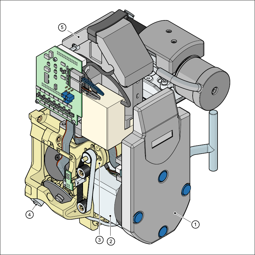
Fig. 3.8 - 4 6-segment Collect&Place head - Function groups, part 2
3
(1) Intermediate distributor board, beneath the cover
(2) Star drive - DR motor
(3) Z axis motor
(4) Valve adjustment drive
(5) 39 x 39 component camera

User Manual SIPLACE S-27 HM 3 Technical data
Software version SR.503.xx 07/2003 US Edition 3.8 Placement heads
95
3.8.2.1 Description
The functionality of the 6-segment revolver head is similar to that of the 12-segment revolver
head. With its standard vision module, the 6-segment revolver head can quickly and accurately
place ICs with an edge length of up to 32 mm x 32 mm. It really comes into its own when there is
a very high proportion of ICs in the placement process. The cycle time of the 6-segment revolver
head depends on the dimensions and number of component leads or bumps.
3.8.2.2 Technical data
3
Component range 0603 to 32 mm x 32 mm,
PLCC, SO, QFP, TSDP, SOT, MELF,
CHIP, IC, BGA
Component specification
Max. height
Min. lead pitch
Min. bump pitch
Min. ball/bump diameter
Min. dimensions
Max. dimensions
Max. weight
8.5 mm (10.7 mm available upon request)
0.5 mm
0.56 mm
0.32 mm
1.6 mm x 0.8 mm
32 mm x 32 mm
5 g
Programmable set-down force 2.4 to 5.0 N
Nozzle types 8 xx, 9 xx
Max. placement rate 8.750 comp/h
Angular accuracy ± 0.3° / 4 sigma (gantry 1)
± 0.4° / 4 sigma (gantry 2)
Placement accuracy ± 70 µm / 4 sigma (gantry 1)
± 80 µm / 4 sigma (gantry 2)
3 Technical data User Manual SIPLACE S-27 HM
3.9 Vision modules Software version SR.503.xx07/2003 US Edition
96
3.9 Vision modules
3.9.1 Description
Each placement system has
– two component cameras on the placement heads and
– two PCB cameras on the underside of the X axis gantries.
The vision analysis unit is located in the control unit for the placement system. The component
vision module is used to determine:
– the precise position of the components at the nozzle and
– the geometry of the package form.
The PCB vision module uses fiducials on the PCBs to determine:
– the position of the PCB,
– its rotation angle
– and the PCB skew.
The PCB vision module also uses fiducials on the feeder modules to determine the exact pick-up
position of components. This is particularly important for small components.