西门子SIPLACE S-27 HM用户手册.pdf - 第78页
3 Technical data User Manual SIPLACE S-27 HM 3.3 Electrical and pneumat ic connection points S oftware version SR. 503.xx07/2003 US Edition 78 3.3 Electrical and pneuma tic connection point s 3 Fig. 3.3 - 1 Electrical an…

User Manual SIPLACE S-27 HM 3 Technical data
Software version SR.503.xx 07/2003 US Edition 3.2 The line concept
77
3.2 The line concept
3.2.1 Overview
The placement system can be linked to input and output stations, screen printing systems, sol-
dering ovens and other automatic placement systems from the SIPLACE range. All SIPLACE
modules are provided with the necessary data by the UNIX line computer or the SIPLACE Pro
computer as appropriate. The placement system can also be linked to a higher level data pro-
cessing system through the use of suitable interfaces.
3.2.2 Technical data – line concept
3
*) SIPLACE 80 S-20 or SIPLACE 80 F4 with 12-segment Collect&Place head
**) SIPLACE S-25 HM / SIPLACE S-27 HM
***) SIPLACE 80 F4/F5/F5 HM
****) SIPLACE HF / SIPLACE HS-60 / HS-50, SIPLACE S-23 HM / S-25 HM / S-27 HM / SIPLACE F5 HM (DCA
option)
*****) SIPLACE HF
System SIPLACE placement lines
Modules SIPLACE HF / SIPLACE HS-60 / SIPLACE HS-50 /
SIPLACE 80 S-20 / SIPLACE S-23 HM
SIPLACE 80 F4 / SIPLACE F5 / SIPLACE F5 HM,
SIPLACE S-25HM / S-27 HM
Peripherals Input/output stations
Screen printers
Soldering ovens
Inspection stations, etc.
Component range From 0402 * to 32 mm x 32 mm ** or
From 0402 * to 55 mm x 55 mm ***
From 0201 **** to 200 mm x 125 mm *****
PCB conveyor Automatic width adjustment
PCB format (length x width) 50 mm x 50 mm to 508 mm x 460 mm
(2" x 2" to 20" to 18")
Placement rate Depends how modules are connected in series
Space required 4 m² / SIPLACE S/F
7.5 m² / SIPLACE HS
3 Technical data User Manual SIPLACE S-27 HM
3.3 Electrical and pneumatic connection points Software version SR.503.xx07/2003 US Edition
78
3.3 Electrical and pneumatic connection points
3
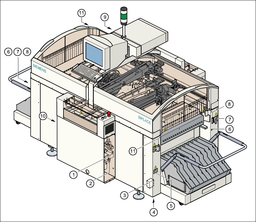
Fig. 3.3 - 1 Electrical and pneumatic connection points on the placement system
(1) Compressed air unit
(2) Connection for compressed air line
(3) Main power filter Z1
(4) Hole for power cable
(5) Service socket
(6) Compressed air connection for component trolleys
(7) Power supply connection for component trolley
(8) Communications connection for component trolley
(9) LAN connection in the control unit
(10) Main switch
(11) Control cable connection for matrix tray changer
User Manual SIPLACE S-27 HM 3 Technical data
Software version SR.503.xx 07/2003 US Edition 3.3 Electrical and pneumatic connection points
79
WARNING
The placement system is supplied with 3 x 400 VAC or 3 x 208 VAC US version) ± 5%, 50/60 Hz
main power voltage. This means that some parts of the system carry potentially lethal voltages -
even when switched off at the main power switch. Death, serious injury or considerable damage
may result if this automatic placement system is handled incorrectly. 3
WARNING
Never disconnect compressed air lines while they are pressurized. Risk of injury. 3