西门子SIPLACE S-27 HM用户手册.pdf - 第108页
4 Setting up t he placement machine User Manual SIPLACE S-27 H M 4.3 Converting the com ponent trolley for other PCB transport height s Software v ersion SR.503.xx07/2003 US Edition 108 4.3 Converting the componen t trol…
User Manual SIPLACE S-27 HM 4 Setting up the placement machine
Software version SR.503.xx 07/2003 US Edition 4.2 Setting up the placement machine
107
4.2 Setting up the placement machine
Æ Raise the placement machine using the fork-lift truck, and adjust the feet until there is a gap of
830 mm between the top edge of the PCB conveyor and the bottom edge of the feet.
Æ Leave a gap of 1 to 3 mm between the PCB conveyors of the placement machine.
Æ Align all the placement machines exactly in line with one another. Use a cord pulled tight to
ensure this.
Æ Adjust each placement machine using a spirit level with an accuracy of 0.02 mm/m.
Æ Lock the feet in position.
Æ Check the placement machine again using the spirit level and correct the settings, if necessary.
CAUTION
Make sure that you remove all the shipping braces from the placement machine. 4
Æ Fit any components that were dismantled for dispatch.
Æ Connect all the electrical and pneumatic lines.
RISK OF DEATH
The electrical connection work MUST be carried out only by appropriately trained and cer-
tified personnel. 4
4 Setting up the placement machine User Manual SIPLACE S-27 HM
4.3 Converting the component trolley for other PCB transport heights Software version SR.503.xx07/2003 US Edition
108
4.3 Converting the component trolley for other PCB
transport heights
4.3.1 Tools
Allen key, set up to 8 mm
4.3.2 Safety instructions
WARNING DANGER OF CRUSHING
Remove all the feeders from the table bed before you change the height of the table on the com-
ponent trolley. Take care during the conversion work because the table bed is very heavy. 4
4
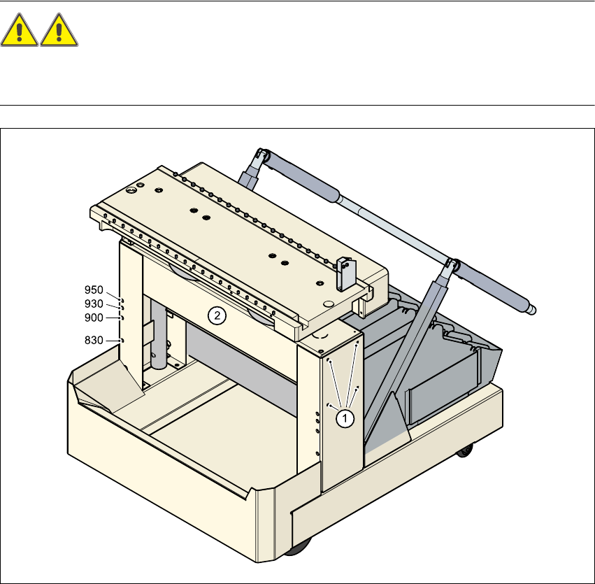
Fig. 4.3 - 1 Converting the component trolley for another PCB transport height
(1) Clamping screws, 4 on each side
(2) Holes in the cross-beam for setting the table height to 830, 900, 930 and 950 mm

User Manual SIPLACE S-27 HM 4 Setting up the placement machine
Software version SR.503.xx 07/2003 US Edition 4.3 Converting the component trolley for other PCB transport heights
109
Æ Insert the two Allen keys (8 mm) into the holes for the current PCB transport height (see Fig.
4.3 - 1
).
Æ Loosen the four clamping screws on each side of the component trolley (see point 1 in Fig. 4.3
- 1).
Æ Ask two people to help you raise and lower the table bed. They should hold the table bed while
you remove the two Allen keys.
Æ Raise or lower the table bed to the required PCB transport height.
Æ Push the two Allen keys (8 mm) into the holes for the new transport height.
Æ Turn the Allen keys so that the cross-beam (item 2 in Fig. 4.3 - 1) is seated on the edge of the
key. The Allen keys can then be removed easily after fixing the cross-beam.
Æ Fix the cross-beam on both sides using the four clamping screws (item 1 in Fig. 4.3 - 1).
Æ Now turn the Allen keys slightly and pull them out.