西门子SIPLACE S-27 HM用户手册.pdf - 第83页
User Manual SIPLAC E S-27 HM 3 Technical data Software vers ion SR.503.xx 07/ 2003 US Edition 3.6 Controls 83 3.6 Controls 3.6. 1 Ove rview 3 Fig. 3.6 - 1 Controls (1) Op erator pane l, input conv eyor (2) Emergen cy sto…
3 Technical data User Manual SIPLACE S-27 HM
3.5 Dimensions and weight of the placement system Software version SR.503.xx07/2003 US Edition
82
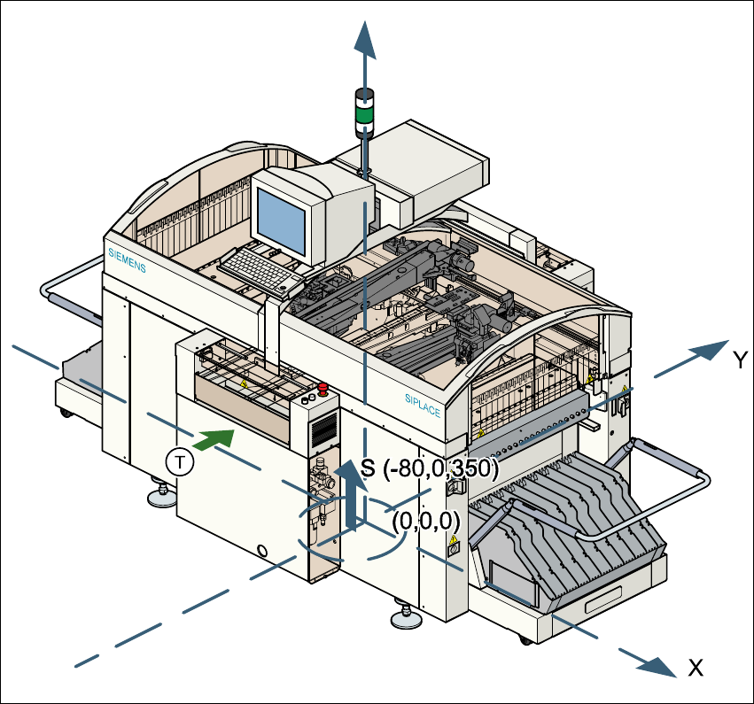
3.5.3 The placement system’s center of gravity
3
Fig. 3.5 - 2 The placement system’s center of gravity
X coordinate - 80 mm
Y coordinate 0 mm
Z coordinate 350 mm high
T PCB transport direction
These center of gravity coordinates relate to placement systems with a PCB transport height of
830 mm.
User Manual SIPLACE S-27 HM 3 Technical data
Software version SR.503.xx 07/2003 US Edition 3.6 Controls
83
3.6 Controls
3.6.1 Overview
3
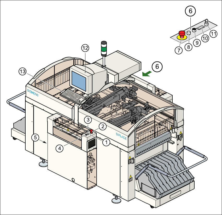
Fig. 3.6 - 1 Controls
(1) Operator panel, input conveyor (2) Emergency stop button
(3) Start button (white) (4) Stop button (black)
(5) Main switch (6) Operator panel, output conveyor
(7) Emergency stop button (8) Start button (white)
(9) Stop button (black) (10) Component counter
(11) Key-operated switch (12) Touchscreen
(13) Keyboard with trackball 3

3 Technical data User Manual SIPLACE S-27 HM
3.6 Controls Software version SR.503.xx07/2003 US Edition
84
3.6.2 Description
All the controls can be reached by a 1.60 m tall person.
Main switch
The main switch is used to switch the power supply to the placement system on and off.
RISK OF DEATH
Some parts inside the placement system carry potentially lethal voltages - even when switched off
at the main switch. 3
Key switch
In normal mode, the key switch is set to "0". The key should be removed and kept in a safe place.
It must only be turned to position "I" (set-up mode) by authorized personnel, and then only for
certain maintenance and servicing work.
Stop button
This button is used to stop the placement system.
Start button
This button starts the placement system after it has been switched on or after faults have been
eliminated.
Emergency stop button
The emergency stop button latches in the ON position when pressed. The power supply to the
gantry axes, the components changeover tables, conveyors, and used tape cutters is interrupted
and the voltage supplied to the star axes of the placement heads is reduced. Turn the button to
release it.
Component counter
The component counter displays the number of components processed.
Station computer, monitor and keyboard
The station computer, monitor and keyboard are mounted on a pivoting console on the place-
ment system’s central crossbeam. The station computer is a desktop model with a Pentium pro-
cessor. The operating system is WINDOWS NT 4.0. The SIPLACE graphical user interface,
which is based on the Windows standard, is used to operate and monitor the placement system.