西门子SIPLACE S-27 HM用户手册.pdf - 第180页
7 Station extensions User Manual S IPLACE S-27 H M 7.5 Ceramic substrate centering Software version SR.503.xx07/2003 US E dition 180 Fig. 7.5 - 1 Ceramic substr ate centering (side view) 7 (1) Mechanic al cer amic su bst…

User Manual SIPLACE S-27 HM 7 Station extensions
Software version SR.503.xx 07/2003 US Edition 7.5 Ceramic substrate centering
179
7.5 Ceramic substrate centering
7.5.1 General
The ceramic substrate can be centered either mechanically or optically.
The position of the fiducials on the ceramic substrates can be detected either with
– the sub-gantry PCB camera with normal lighting that is fitted as standard, or
– using the multi-color PCB camera (option).
7.5.2 Mechanical centering
7.5.2.1 General
Mechanical substrate centering is used to lock ceramic substrates firmly in position in the X and
Y directions in such a way that the material is not damaged. Ceramic substrates can also be
placed right up to the edge.
7.5.2.2 Assembling and dismantling the ceramic substrate centering unit
PLEASE NOTE 7
The ceramic substrate centering unit must only be assembled and dismantled by service engi-
neers. 7
7 Station extensions User Manual SIPLACE S-27 HM
7.5 Ceramic substrate centering Software version SR.503.xx07/2003 US Edition
180
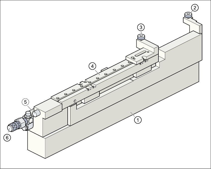
Fig. 7.5 - 1 Ceramic substrate centering (side view)
7
(1) Mechanical ceramic substrate centering
(2) Stop
(3) Ball bearing
(4) Centering slide
(5) Proximity switch connecting cable
(6) Compressed air connection
7.5.2.3 Maintenance
– Clean and grease the ball race in the X axis centering unit.
– If necessary, check that the pneumatic driving mechanism is running smoothly.
– The conveyor should be maintained as described in the maintenance instructions.

User Manual SIPLACE S-27 HM 7 Station extensions
Software version SR.503.xx 07/2003 US Edition 7.5 Ceramic substrate centering
181
7.5.3 Technical data
7
7
Substrate format 50 mm x 50 mm to 100 mm x 180
mm
Substrate thickness 0.5 mm to 1.5 mm
Substrate model Unscribed (without problems)
Scribed (requires testing)
Support on the conveyor 2.5 mm
Optical centering: field of view of the PCB vision module
Type of illumination for light pastes:
Type of illumination for dark pastes and close
spacing to adjacent structures (> 1 mm):
5.7 mm x 5.7 mm
PCB camera (standard)
Multicolor camera (option)
(4 illumination levels to be selected)
Fiducial criteria See PCB vision module position
detection
Mechanical centering:
X/Y centering accuracy ± 0.07 mm / 4 sigma
PCB underside clearance 12 mm
Compressed air connection 0.55 MPa (5.5 bar)