西门子SIPLACE S-27 HM用户手册.pdf - 第90页
3 Technical data User Manual SIPLACE S-27 HM 3.8 Placement heads Software version SR.503.xx07/2003 US Edition 90 3.8 Placem ent heads 3.8.1 12-segment Collect &Place hea d with st andard compone nt camera 3 Fig. 3.8 …

User Manual SIPLACE S-27 HM 3 Technical data
Software version SR.503.xx 07/2003 US Edition 3.7 Gantries
89
3.7.3 Technical data for the X axis
3
3.7.4 Structure of the Y axis
The Y axis essentially consists of the following main modules:
– Y axis three-phase AC servomotor
– Y axis toothed belt
– Y axis guide system
– Y axis measuring system
Each Y axis is driven by a three-phase AC servomotor. An anti-crash circuit prevents the travers-
ing paths of the gantries meeting.
3.7.5 Technical data for the Y axis
3
Drive Three-phase AC servomotor/toothed belt
Maximum speed 2.5 m/sec.
Traversing path 620 mm
Distance measuring system Metal linear scale
Scale length 646 mm
Resolution 1 µm
Drive Three-phase AC servomotor/toothed belt
Maximum speed 2.5 m/sec.
Traversing path 942 mm
Distance measuring system Metal linear scale
Scale length 1002 mm
Resolution 1 µm
3 Technical data User Manual SIPLACE S-27 HM
3.8 Placement heads Software version SR.503.xx07/2003 US Edition
90
3.8 Placement heads
3.8.1 12-segment Collect&Place head with standard component camera
3
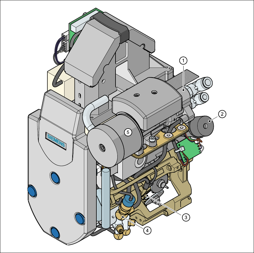
Fig. 3.8 - 1 12-segment Collect&Place head - Function groups, part 1
3
(1) Vacuum generator
(2) Turning station, DP axis
(3) Star with 12 sleeves, DR axis
(4) Forced air valve
(5) Silencer
User Manual SIPLACE S-27 HM 3 Technical data
Software version SR.503.xx 07/2003 US Edition 3.8 Placement heads
91
3
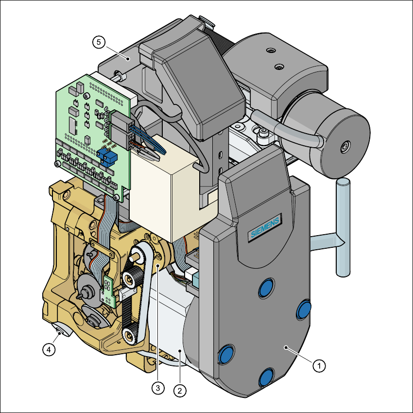
Fig. 3.8 - 2 12-segment Collect&Place head - Function groups, part 2
3
(1)Intermediate distributor board (beneath the cover)
(2)Star drive - DR motor
(3)Z axis motor
(4)Valve adjustment drive
(5)24 x 24 component camera