西门子SIPLACE S-27 HM用户手册.pdf - 第74页
3 Technical data User Manual SIPLACE S-27 HM 3.1 Description of the m achine Software version SR. 503.xx07/2003 US Edition 74 The placem ent hea ds fetch com ponents from stationary feeders and place th em in th e PCBs c…
User Manual SIPLACE S-27 HM 3 Technical data
Software version SR.503.xx 07/2003 US Edition 3.1 Description of the machine
73
3 Technical data
3.1 Description of the machine
The automatic placement system is a high-performance placement system with two gantries. A
PCB camera and a 6 or 12-segment Collect&Place-head are mounted on each gantry.
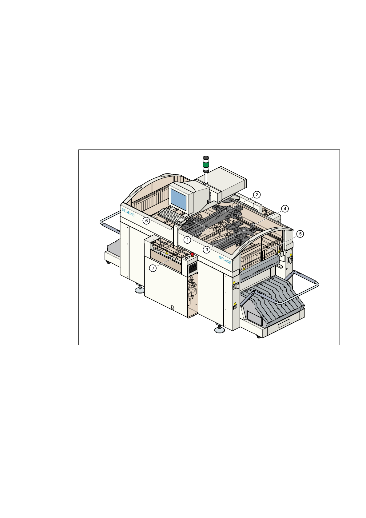
Fig. 3.1 - 1 Overall view of the placement system
(1) 6/12-segment Collect&Place head with component camera (gantry 1)
(2) Gantry 1 with PCB camera
(3) 6/12-segment Collect&Place head with component camera (gantry 2)
(4) Gantry 2 with PCB camera
(5) Stationary component supply (location 1)
(6) Stationary component supply (location 3)
(7) PCB conveyor (dual conveyor option)

3 Technical data User Manual SIPLACE S-27 HM
3.1 Description of the machine Software version SR.503.xx07/2003 US Edition
74
The placement heads fetch components from stationary feeders and place them in the PCBs
clamped on the PCB conveyor.
The concept behind the automatic placement system
– with its stationary feeders,
– PCBs that do not move during placement
– and positionable placement heads
has a number of significant benefits:
– For example, the flexible 6/12-segment Collect&Place heads combined with automatic nozzle
changers enable the nozzle configuration to be changed temporarily and automatically
adapted to receive different component sizes. You can also optimize the traversing paths and
the placement sequence.
– With stationary feeders, even the tiniest components are picked up reliably.
– The components cannot slip on the PCB during placement (as is often the case with moving
PCBs) since the PCB does not move.
– Sophisticated optical centering systems (vision modules) for components and PCBs also en-
sure high component positioning accuracy.
– Components can be topped up and tapes can be spliced without stopping the machine.
– Prepared component trolleys enable the placement system to be retooled without long stop-
pages.
3.1.1 Head Modularity concept (HM)
The abbreviation HM in the designation of the SIPLACE S-27 HM placement system stands for
Head Modularity.
This concept allows any combination of 6-nozzle and 12-nozzle Collect&Place heads to be used
on the placement system. A simple head change procedure will enable the system to be quickly
adapted to the requirements of individual placement jobs.

User Manual SIPLACE S-27 HM 3 Technical data
Software version SR.503.xx 07/2003 US Edition 3.1 Description of the machine
75
3.1.2 Technical data - machine overview
3
Placement procedure Collect&Place
Component range
*)
12-segment Collect&Place head with
standard component camera
Max. component height
12-segment Collect&Place head with
DCA camera
Max. component height
6-segment Collect&Place head with
standard component camera
Max. component height
6-segment Collect&Place head with
DCA camera
Max. component height
From 0.6 mm x 0.3 mm up to 18.7 mm x 18.7 mm
(0201 up to PLCC44, SO32, DRAM)
6 mm (10.7 mm available upon request)
From 0.6 mm x 0.3 mm up to 13 mm x 13 mm
(0201, flip-chip)
6 mm (10.7 mm available upon request)
From 1.6 mm x 0.8 mm up to 32 mm x 32 mm
(0603 or larger)
8.5 mm (10.7 mm available upon request)
From 0.6 mm x 0.3 mm up to 13 mm x 13 mm
(0201, Flip-chip)
8.5 mm (10.7 mm available upon request)
Maximum placement rate (Benchmark)
with two 12-segment Collect&Place heads
with one 6-segment and one 12-segment-
Collect&Place head
with two 6-segment Collect&Place heads
26.500 components/h
19.500 components/h
17,500 components/h
12-segment Collect&Place head
Angular accuracy
Placement accuracy
± 0.7°/ 4 sigma
90 µm / 4 sigma
6-segment Collect&Place head
Angular accuracy
Placement accuracy
± 0.3°/ 4 sigma (gantry 1)
± 0.4°/ 4 sigma (gantry 2)
± 70 µm / 4 sigma (gantry 1)
± 80 µm / 4 sigma (gantry 2)
PCB format
Single conveyor system (length x width)
Dual conveyor system (length x width)
50 mm x 50 mm to 508 mm x 460 mm
(2" x 2" to 20" x 18")
long board: up to 610 mm (24") (option)
50 mm x 50 mm to 508 mm x 216 mm
(2" x 2" to 20" x 8.5")
long board: up to 610 mm (24") (option)
PCB thickness 0.5 mm to 4.5 mm
PCB changeover time 2.5 sec
Feeder capacity 118 x 8 mm tracks