西门子SIPLACE S-27 HM用户手册.pdf - 第50页
2 Operational safety User Manual SIPLACE S-27 HM 2.5 Safety equipment Software v ersion SR.503.xx07/2003 US Edition 50 2.5 S afety equipment 2.5.1 Protectiv e cove rs Fig. 2.5 - 1 Safety equipment in t he placement machi…

User Manual SIPLACE S-27 HM 2 Operational safety
Software version SR.503.xx 07/2003 US Edition 2.4 Safety instructions for operating the machine
49
WARNING 2
Æ NEVER place your hand in the gaps between the matrix tray changer and machine frame (item
1) while the machine is running.
Æ Always couple the matrix tray changer to the machine before connecting or disconnecting the
matrix tray changer control cable at the machine socket (item 2).
Æ Always couple the matrix tray changer to the machine before connecting or disconnecting the
control cable for the matrix tray changer’s integral component feeder table at the machine
socket (item 3).
Æ Always couple the matrix tray changer to the machine before connecting or disconnecting the
power cable from the external power supply (item 4).
Æ NEVER operate the matrix tray changer if it is not coupled to the machine.
2 Operational safety User Manual SIPLACE S-27 HM
2.5 Safety equipment Software version SR.503.xx07/2003 US Edition
50
2.5 Safety equipment
2.5.1 Protective covers
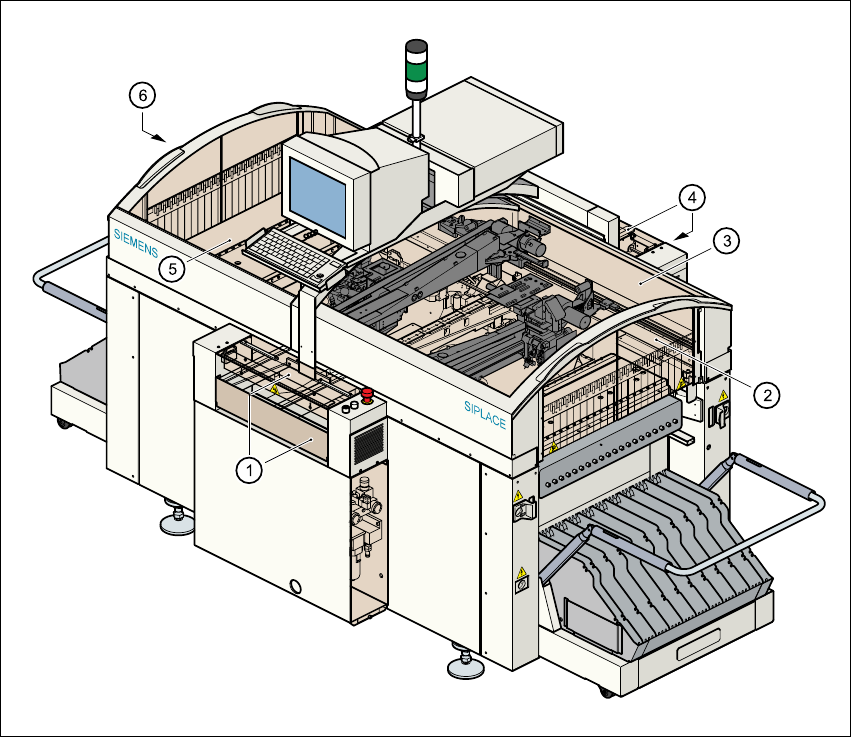
Fig. 2.5 - 1 Safety equipment in the placement machine
(1) Cover and guard on the input belt
(2) Safety panels, right-hand side
(3) Protective cover
(4) Cover and guard on the output conveyor
(5) Protective cover
(6) Safety panels, left-hand side
User Manual SIPLACE S-27 HM 2 Operational safety
Software version SR.503.xx 07/2003 US Edition 2.5 Safety equipment
51
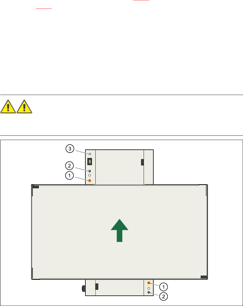
The gantry positioning range is covered by two protective covers. If you want to open the protec-
tive covers, first press the Stop button (item 1 in Fig. 2.5 - 2
) or the emergency stop button
(item 2 in Fig. 2.5 - 2
). The power to the gantry axes will be switched off and the gantries will stop
immediately.
If you open one of the protective covers or a guard on the incoming or outgoing conveyor, the
power to the gantry axes will be switched off. They will stop immediately.
If the key switch is closed (position I), you can continue to pace the star at reduced speed while
the protective covers are open.
Placement will stop if you press the emergency stop button. You can then either cancel or con-
tinue placement of the PCB. The protective covers at the sides can be opened in order to refill
with components when the machine has stopped.
WARNING
The protective covers must only be opened, with the key switch closed (position I), by appropri-
ately qualified and trained personnel. 2
Fig. 2.5 - 2 Stop and EMERGENCY STOP buttons, key-operated switch
(1) Emergency stop button
(2) Stop button
(3) Key-operated switch