西门子SIPLACE S-27 HM用户手册.pdf - 第186页
7 Station extensions User Manual S IPLACE S-27 H M 7.6 Fine calibration Software version SR.503.xx07/2003 US Edition 186 7.6 Fine calibration 7.6.1 Overvie w Fine ca libration i nvolve s measurin g the ma chin e’s placem…

User Manual SIPLACE S-27 HM 7 Station extensions
Software version SR.503.xx 07/2003 US Edition 7.5 Ceramic substrate centering
185
– Blue oblique lighting:
In most cases, this can be used to greatly improve the contrast with bright fiducials on a light
base material, such as ceramic or CEM (c
omposite electrochemical materials). Fiducials cov-
ered with solder resist can also be detected better on a light background.
– Infrared lighting
This type of illumination is particularly useful for fiducials that are covered with solder resist or
for fiducials on flex materials. It is also sometimes possible to improve detection of silver/plat-
inum fiducials on ceramic. This should be tested by carrying out a test centering or placement
run.

7 Station extensions User Manual SIPLACE S-27 HM
7.6 Fine calibration Software version SR.503.xx07/2003 US Edition
186
7.6 Fine calibration
7.6.1 Overview
Fine calibration involves measuring the machine’s placement offset and determining the required
correction from this value. The ‘Fine calibration’ measuring program is integrated into the SIT-
EST program, and a detailed description of the measuring procedure is given in the ‘Fine calibra-
tion’ instructions (article no. 00191655-01).
CAUTION
The SITEST program is password-protected. It must only be called up and used by
SIEMENSDEMATIC engineers or appropriately trained personnel. 7
7.6.2 System requirements
The following system requirements must be fulfilled in order to use the fine calibration program:
Machine type S-27 HM
Station computer software version 503.xx or later
SITEST version 503.xx or later
PLEASE NOTE: 7
The fine calibration can only be carried out with the 12-segment Collect&Place head. 7
7.6.3 Measuring equipment and tools
The following are supplied as standard:
– Mapping plate (glass plate in a metal frame)
– Double-sided transparent adhesive film
– Lighting unit
– CERAM components in the feeder for the 12-segment Collect&Place head
User Manual SIPLACE S-27 HM 7 Station extensions
Software version SR.503.xx 07/2003 US Edition 7.6 Fine calibration
187
7.6.4 Description of the functions
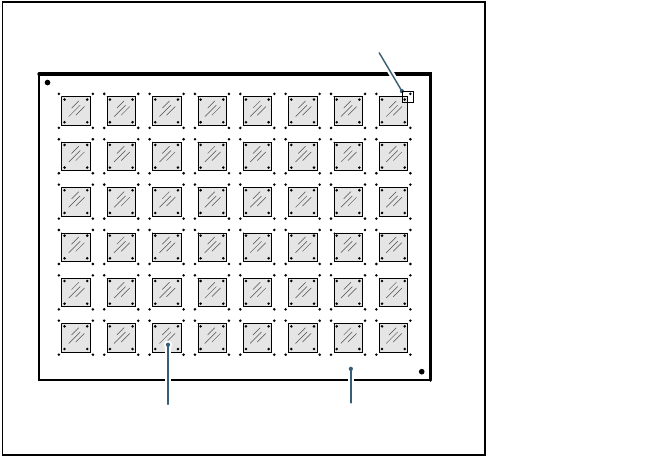
A large number of CERAM components are placed on a glass PCB covered with adhesive film.
On the top of the CERAM components there are reference fiducials in each corner. The glass
PCB also has reference fiducials in the immediate vicinity of these component fiducials.
Fig. 7.6 - 1 Fine calibration principle
Immediately after placement, the PCB camera takes four sets of images of the associated refer-
ence fiducials on both PCB and component. The analysis program is then used to determine the
placement offset in the X/Y direction and the angular deviation. The offset values are used to cal-
culate the corrected values, which are then entered in the machine data (FK_off.ma).
7.6.5 Measuring modes
The following measurement modes can be selected:
– Measure the values for an individual placement head.
– Measure the values for all the placement heads in a placement area.
– Measure the values for the entire machine.
The measurement can be repeated as often as required, with or without replacing the CERAM
components.
Glass components Glass PCB
Field of view of the PCB camera