西门子SIPLACE S-27 HM用户手册.pdf - 第208页
7 Station extensions User Manual S IPLACE S-27 H M 7.12 SIPLACE pr oductivity lift Software version SR.503.xx07/2003 US Edition 208 7.12. 4 T echnica l dat a 7 Supply vol tage 230/400 VA C, 110/2 30 VAC, ± 10%, 50/60 Hz …
User Manual SIPLACE S-27 HM 7 Station extensions
Software version SR.503.xx 07/2003 US Edition 7.12 SIPLACE productivity lift
207
7.12.3 Advantages of the productivity lift
The productivity lift can raise the productivity of a line overall because it increases the placement
rates of the machines on the line.
7
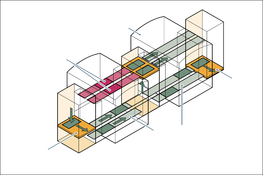
Fig. 7.12 - 3 Productivity lift – avoiding stoppages
7
If lines are connected in parallel, individual machines may fail without bringing the entire line to a
standstill. It is also possible access individual machines while the rest of the line continues plac-
ing without interruption.
This could be for
– process-related investigations or test operation
– programming PCB fiducials, package forms or test placements
– maintenance or repairs
– operating errors, such as not splicing tapes on in good time or missing components.
Another advantage is that the line can be reconfigured as required using the software, without
having to reset the machines.
PCB conveyor section,
processing
Placement machine
Horizontal
and vertical lift
Underfloor
conveyor
Track change

7 Station extensions User Manual SIPLACE S-27 HM
7.12 SIPLACE productivity lift Software version SR.503.xx07/2003 US Edition
208
7.12.4 Technical data
7
Supply voltage 230/400 VAC, 110/230 VAC, ± 10%, 50/60 Hz
Total connected load 0.5 kVA
Total power 0.5 kW (2 A connected load)
Fuses 6.3 A
Power failure Max. 20 msec
Compressed air connection Min. 0.5 MPa (5.0 bar), 10 Nl/min
Length of the conveyor section 1595 mm
Length of the HV shuttle 540 mm
Width of the HV shuttle 1045 mm
Height of the HV shuttle 1200 mm (for conveyor height of 930 mm)
Weight of the HV shuttle 212 kg
Weight of the underfloor section 90 kg
Permissible load per unit area on foundation Min. 0.2 t/m²
Room temperature Between 15 °C and 35 °C
Atmospheric humidity 30 - 70%, but no higher than 45% on average in
order to prevent any possibility of condensation
on the machine.
Max. noise generated 62 dBA
PCB conveyor height 930 ± 30 mm
PCB dimensions
Width
Length
Thickness
50 mm - 216 mm (2" – 8.5")
50 mm 460 mm (2" 18")
0.5 mm - 4.5 mm

User Manual SIPLACE S-27 HM Index
07/2003 US Edition
209
Index
12 mm S feeder for capacitors based on powdered
metal
model C/D
137
model E
138
12/16 mm S feeder
136
12-segment Collect&Place head
75
24 x 24 component camera
91
angular accuracy
75
forced air valve
90
intermediate distributor board
91
placement accuracy
75
silencer
90
star drive - DR motor
91
star with 12 sleeves, DR axis
90
turning station, DP axis
90
vacuum generator
90
valve adjustment drive
91
Z axis motor
91
12-segment Collect&Place head with DCA camera
197
angular accuracy
198
component specification
198
description
198
max. placement rate
198
nozzle types
198
placement accuracy
198
programable set-down force
198
range of components
198
technical data
198
12-segment Collect&Place head with standard com-
ponent camera
90
angular accuracy
92
component specifications
92
description
92
max. placement rate
92
nozzle types
92
placement accuracy
92
programable set-down force
92
range of components
92
technical data
92
24/32 mm S feeder
139
3 x 8 mm S feeder
134
3 x 8 mm S feeder for 0201/0402 CO
135
44 mm S feeder
140
6/12-segment Collect&Place head
73
6-segment Collect&Place head
75
39 x 39 component camera
94
angular accuracy
75
forced air valve
93
intermediate distributor board
94
placement accuracy
75
silencer
93
star drive - DR motor
94
star with 6 sleeves, DR axis
93
turning station, DP axis
93
vacuum generator
93
valve adjustment drive
94
with DCA camera
200
Z axis motor
94
6-segment Collect&Place head with DCA camera
angular accuracy
201
component specification
201
description
201
max. placement rate
201
nozzle types
201
placement accuracy
201
programable set-down force
201
range of components
201
technical data
201
6-segment Collect&Place head with standard com-
ponent camera
93
angular accuracy
95
component specifications
95
description
95
max. placement rate
95
nozzle types
95
placement accuracy
95
programable set-down force
95
range of components
95
technical data
95
8 mm S II feeder
133
A
abbreviations
21
ambient factors, permitted
80
asynchronous conveyor mode
172
description
172