西门子SIPLACE S-27 HM用户手册.pdf - 第72页
2 Operational safety User Manual SIPLACE S-27 HM 2.11 ESD guidelines Software version SR.503.xx07/2003 US Edition 72
User Manual SIPLACE S-27 HM 2 Operational safety
Software version SR.503.xx 07/2003 US Edition 2.11 ESD guidelines
71
Always discharge yourself before you touch an electronic module. To do this, simply touch a con-
ductive and earthed object immediately before you touch the module (such as unpainted parts of
a switch cabinet, a water pipe, etc.).
Do not allow modules with chargeable and highly insulating materials to touch one another, e.g.
plastic films, insulating table surfaces or items of clothing made from synthetic fibers.
Always place the modules on a conductive surface (table with an ESD coating, conductive ESD
foam, ESD bag or container).
Do not bring modules near visual display units, monitors or televisions. Keep them at least 10 cm
away from the screen.
2.11.4 Measurements and modifications to ESD modules
Do not take measurements on such modules unless
– the measuring device is earthed (e.g. via PE conductors) or
– you discharge the measuring head just before taking measurements with a potential-free mea-
suring device (e.g. by touching an unpainted metal part of the controller casing).
Æ Always use an earthed soldering iron if you carry out any soldering work.
2.11.5 Dispatching ESD modules
Always store modules and components in conductive packaging (e.g. metallized plastic bags or
metal sleeves) and dispatch them in conductive packaging.
If the packaging is not conductive, place the modules in a conductive envelope before packag-
ing. (Use ESD bags, domestic aluminum foil or paper, for example. NEVER use plastic bags or
film).
If the module has integral batteries, ensure that the conductive packaging does not touch or
short-circuit the battery terminals and, if necessary, first cover the terminals with insulating tape
or material.
2 Operational safety User Manual SIPLACE S-27 HM
2.11 ESD guidelines Software version SR.503.xx07/2003 US Edition
72
User Manual SIPLACE S-27 HM 3 Technical data
Software version SR.503.xx 07/2003 US Edition 3.1 Description of the machine
73
3 Technical data
3.1 Description of the machine
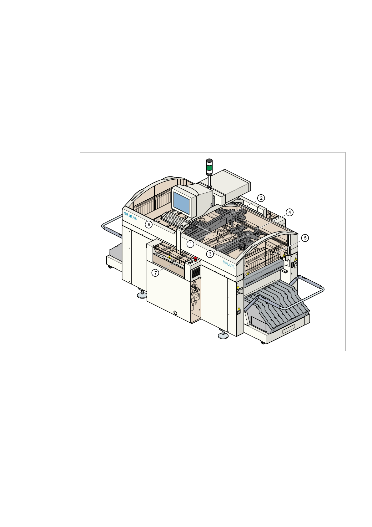
The automatic placement system is a high-performance placement system with two gantries. A
PCB camera and a 6 or 12-segment Collect&Place-head are mounted on each gantry.
Fig. 3.1 - 1 Overall view of the placement system
(1) 6/12-segment Collect&Place head with component camera (gantry 1)
(2) Gantry 1 with PCB camera
(3) 6/12-segment Collect&Place head with component camera (gantry 2)
(4) Gantry 2 with PCB camera
(5) Stationary component supply (location 1)
(6) Stationary component supply (location 3)
(7) PCB conveyor (dual conveyor option)