西门子SIPLACE S-27 HM用户手册.pdf - 第77页
User Manual SIPLAC E S-27 HM 3 Technical data Software vers ion SR.503.xx 07/2003 US Edition 3.2 The line concept 77 3.2 The line concept 3.2. 1 Ove rview The pla cement sys tem ca n be link ed to inpu t and output stati…

3 Technical data User Manual SIPLACE S-27 HM
3.1 Description of the machine Software version SR.503.xx07/2003 US Edition
76
*) The S-27 HM can be equipped to place 0201 components. Please consult the factory if you require this.
**) With this conveyor the circuit board is clamped from the underside. The distance from the top of the PCB to the
placement head thus remains constant and the placement rate is independent of the PCB thickness.
Component supply
Types of feeder
Component trolley, matrix tray changer, (see
chapter 6
)
Component tapes, stick magazines, bulk cases,
surf tapes (see chapter 6
)
Operating system Microsoft Windows NT / RMOS
Connection Inline or stand alone
Space required 4 m² / module

User Manual SIPLACE S-27 HM 3 Technical data
Software version SR.503.xx 07/2003 US Edition 3.2 The line concept
77
3.2 The line concept
3.2.1 Overview
The placement system can be linked to input and output stations, screen printing systems, sol-
dering ovens and other automatic placement systems from the SIPLACE range. All SIPLACE
modules are provided with the necessary data by the UNIX line computer or the SIPLACE Pro
computer as appropriate. The placement system can also be linked to a higher level data pro-
cessing system through the use of suitable interfaces.
3.2.2 Technical data – line concept
3
*) SIPLACE 80 S-20 or SIPLACE 80 F4 with 12-segment Collect&Place head
**) SIPLACE S-25 HM / SIPLACE S-27 HM
***) SIPLACE 80 F4/F5/F5 HM
****) SIPLACE HF / SIPLACE HS-60 / HS-50, SIPLACE S-23 HM / S-25 HM / S-27 HM / SIPLACE F5 HM (DCA
option)
*****) SIPLACE HF
System SIPLACE placement lines
Modules SIPLACE HF / SIPLACE HS-60 / SIPLACE HS-50 /
SIPLACE 80 S-20 / SIPLACE S-23 HM
SIPLACE 80 F4 / SIPLACE F5 / SIPLACE F5 HM,
SIPLACE S-25HM / S-27 HM
Peripherals Input/output stations
Screen printers
Soldering ovens
Inspection stations, etc.
Component range From 0402 * to 32 mm x 32 mm ** or
From 0402 * to 55 mm x 55 mm ***
From 0201 **** to 200 mm x 125 mm *****
PCB conveyor Automatic width adjustment
PCB format (length x width) 50 mm x 50 mm to 508 mm x 460 mm
(2" x 2" to 20" to 18")
Placement rate Depends how modules are connected in series
Space required 4 m² / SIPLACE S/F
7.5 m² / SIPLACE HS
3 Technical data User Manual SIPLACE S-27 HM
3.3 Electrical and pneumatic connection points Software version SR.503.xx07/2003 US Edition
78
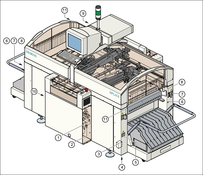
3.3 Electrical and pneumatic connection points
3
Fig. 3.3 - 1 Electrical and pneumatic connection points on the placement system
(1) Compressed air unit
(2) Connection for compressed air line
(3) Main power filter Z1
(4) Hole for power cable
(5) Service socket
(6) Compressed air connection for component trolleys
(7) Power supply connection for component trolley
(8) Communications connection for component trolley
(9) LAN connection in the control unit
(10) Main switch
(11) Control cable connection for matrix tray changer