西门子SIPLACE S-27 HM用户手册.pdf - 第57页
User Manual SIPLAC E S-27 HM 2 Operational safety Software vers ion SR.503.xx 07/2003 US Edition 2.5 Safety equipment 57 Fig. 2.5 - 5 S afety circuits S tart button press ed Emerg . stop button pressed ? Protect ive cove…
2 Operational safety User Manual SIPLACE S-27 HM
2.5 Safety equipment Software version SR.503.xx07/2003 US Edition
56
K1 or K2 is triggered if any of these functions fail. The mains voltage to the heavy current trans-
former that supplies the gantry axis motors will be interrupted. The voltage to the star-type motor
for the Collect&Place head is reduced from 70 V to 10 V. The DP and DR axes of the placement
heads continue to be supplied with 30 V. The next diagram illustrates the various statuses of K1
and K2 and their effects on the axes and the PCB conveyor components.
User Manual SIPLACE S-27 HM 2 Operational safety
Software version SR.503.xx 07/2003 US Edition 2.5 Safety equipment
57
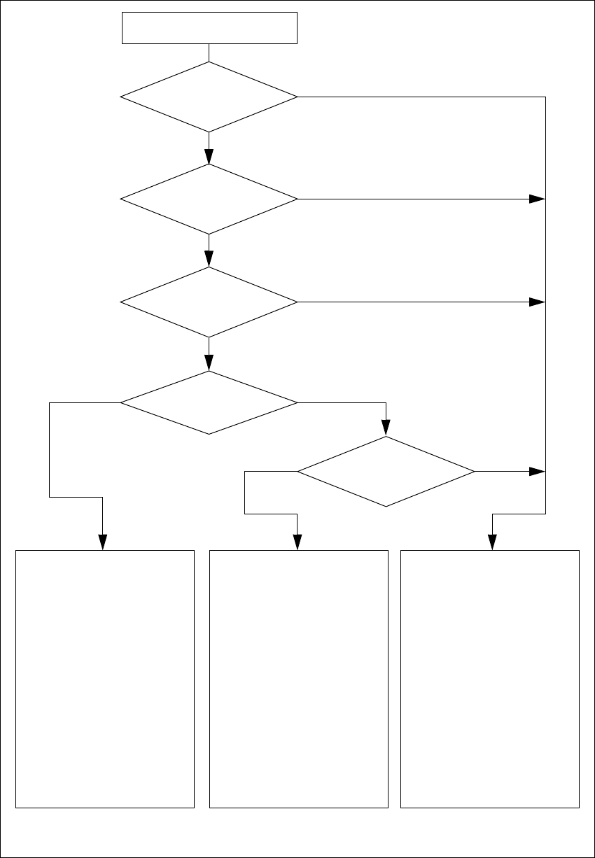
Fig. 2.5 - 5 Safety circuits
Start button pressed
Emerg. stop button
pressed?
Protective cover open ?
Key switch
closed (position I)?
No
Component
table safety circuit
interrupted?
Yes
No
No
Yes
Yes
No
Active
K1 *) Yes
K2 *) Yes
Voltage
Y axis 155 V
X axis 155 V
Star axis 70 V
DP axis 30 V
Z axis 30 V
Active
PCB conveyor Yes
Lifting table Yes
PCB clamping Yes
Width adjustment Yes
Laser light barrier Yes
Tape cutter Yes
Yes
Active
K1 *) No
K2 *) Yes
Voltage
Y axis 0 V
X axis 0 V
Star axis 10 V
DP axis 30 V
Z axis 30 V
Active
PCB conveyor Yes
Lifting table No
PCB clamping No
Width adjustment Yes
Laser light barrier No
Tape cutter No
Active
K1 *) No
K2 *) No
Voltage
Y axis 0 V
X axis 0 V
Star axis 10 V
DP axis 30 V
Z axis 30 V
Active
PCB conveyor No
Lifting table No
PCB clamping No
Width adjustment No
Laser light barrier No
Tape cutter No
*) K1, K2 protective contactor combination
Compressed
air min. 0.55 MPa
(5.5 bar)?
Yes
No
2 Operational safety User Manual SIPLACE S-27 HM
2.5 Safety equipment Software version SR.503.xx07/2003 US Edition
58
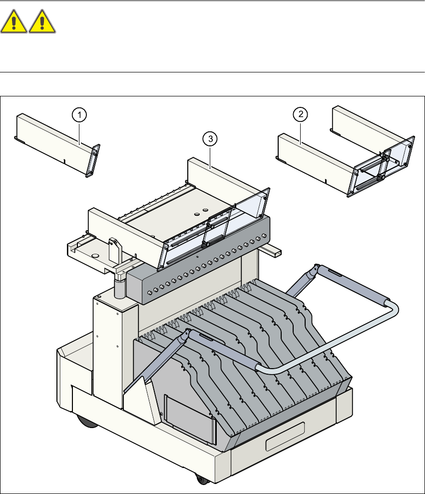
2.5.5 Guard on the component table locations
WARNING 2
All locations must be equipped with feeders in order to guarantee operational reliability. If there
are not enough feeders available, a guard ("dummy feeder") must be fitted in place of the feeder.2
2
Fig. 2.5 - 6 Guard
2
(1) Guard for 1 location part no. 00116961-01
(2) Guard for 6 to 10 locations part no. 00116962-01
(3) Guard for 11 to 20 locations part no. 00116963-01